Origin X/Y – X/Y dimension resulting from the design assumptions of the printed model.
Print X/Y – measured dimension of the printout.
Save – confirmation of changes.
Back – return to previous menu.
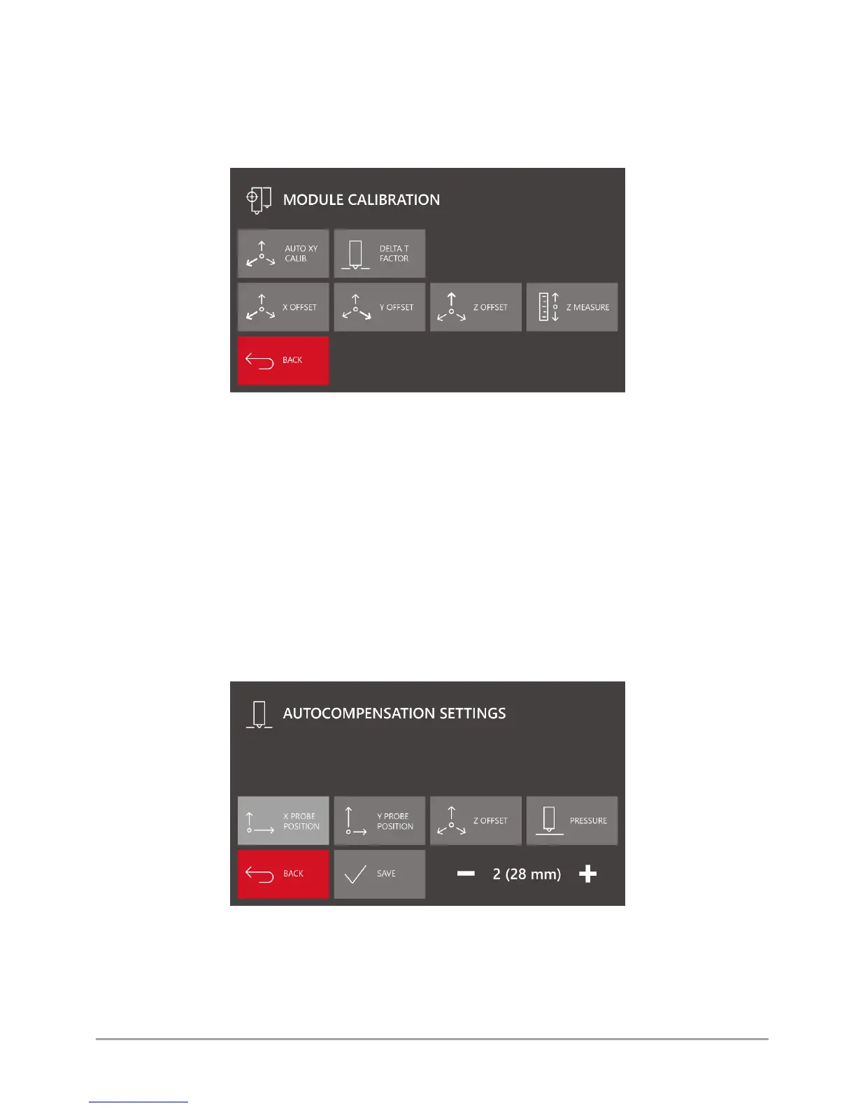
Module calib. - menu of calibration of dual hotend module offsets (fig. 27).
Fig. 27 MODULE CALIBRATION menu screen
Auto XY CALIB. – the option for automatic calibration of offsets between hotends in the X axis and in the Y axis. The procedure
is described in chapter VIII, point 2.2.
Delta T Factor – hotend temperature correction factor. It is recommended to use it when replacing the hotend for maximum
precision of temperature control by the printer. The procedure is described in chapter VI, point 1.
X/Y/Z offset – the options for adjusting the offset values of T1 hotend with regard to the global system. Correct calibration of
these values is crucial for proper functioning of the dual hotend system. More information on offset calibration can be found
in chapter VIII, point 2.2.
Z measure - the option used for checking and setting the correct value of Z Offset. After pressing the "Z MEASURE" key, the
printer will examine the position of T0 hotend tensometrically. Next, in the same place, the printer will make the same
measurement for T1 hotend position. The difference resulting from the measurement will be recorded in Z Offset field.
Save – confirmation of changes.
Back – return to previous menu.
Autocomp. settings - menu of printer autocompensation settings (fig. 28).
Fig. 28 AUTOCOMPENSATION SETTINGS menu screen
X probe position – defines the distance between the autocompensation measuring point and the referencing point along X axis.
Modifying this value, you can move the measuring point along X axis.
Y probe position – defines the distance between the autocompensation measuring point and the referencing point along Y axis.
Modifying this value, you can move the measuring point along Y axis.