11
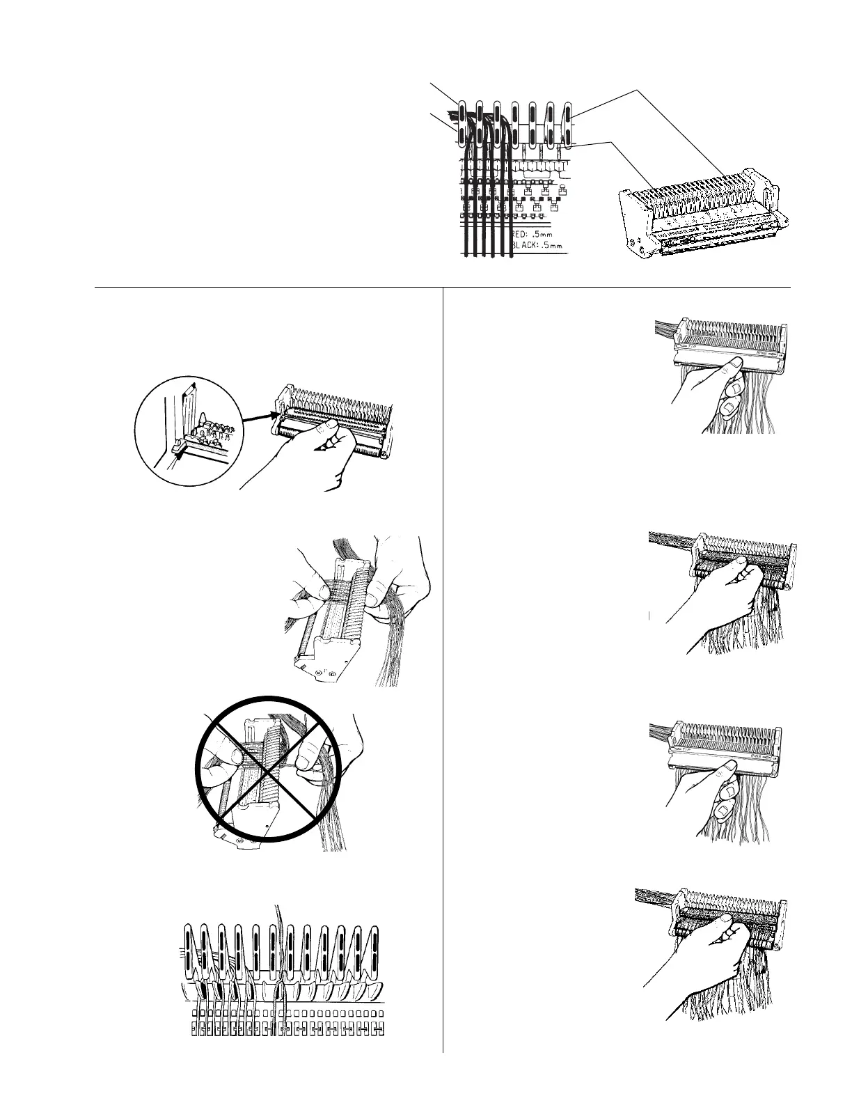
5.2 Wire Placement in Module
Note: Follow Color Code.
5.2.1 Wire pair to right side of
corresponding color coded wire guide.
Separate pair over pair separator, TIP left and
RING right.
Wire Guides
RING colors
TIP Colors
Pair
Separators
843436
843046
5.2.4 Make sure all wires are
lying flat in module
channel.
Check for empty channels,
2 wires in one channel or
reversed pairs.
Slide comb left, only TIP
wires should show. Slide comb right, only
RING wires should show.
5.2.2 Using Super-Mini – Install base
Using Super-Mate – Install body/insulator
812117
5.2.3 Select a 25-pair group
and place wires in
module according to
color code.
Draw wires snug into
wire channels in mod-
ule.
Secure in retainer
springs.
832596
832597
Thumb placed too far from rear of head, could
cause twist in pair resulting in "shiners."
75436
832601
5.2.7 Install module cover.
Module Cut Corner Upper Left
893745
893745
5.2.6 Check for correct
wire placement using
the orange check comb.
5.2.5 Install next module
component.
Place pairs from corre-
sponding group.
832600