39
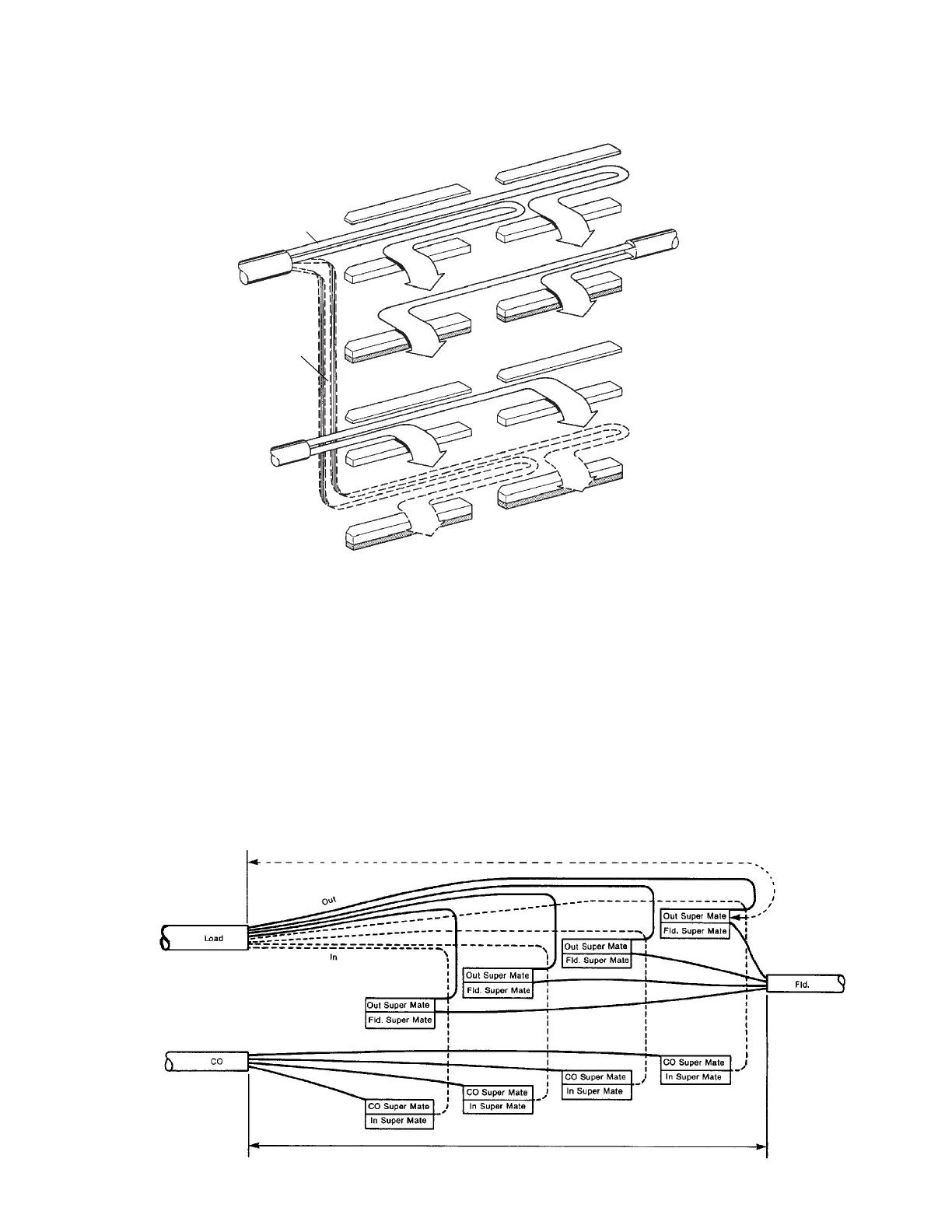
8.7 Load Coil Splice "L" (Apparatus)
This splice is utilized where any apparatus having an "in" and "out" is to be added (i.e., load coil, carrier.)
843059
FIELD
C.O.
"IN"
"OUT"
Inline Splice Method
Inline Splice Method
Body
Body
Insulator
Cover
Cover
Body
Body
Insulator
"IN" Super-Mate
"C.O." Super-Mate
"FIELD" Super-Mate
"OUT" Super-Mate
}
}
}
}
Unilength Splicing Method
Unilength Splicing Method
If apparatus is:
1. Color Coded: Lay into Super-Mate module in color code order.
2. Quaded Pair: Lay "in" and "out" pairs into corresponding position in appropriate Super-Mate modules.
On feeder routes, engineers should note the proper measurements on the work print where equipment could
be added. Construction can then build that splice with Super-Mate Modules for simple plugging and
unplugging as needed in the future.
Load coil splicing requires more modules than regular splicing. Refer to the apparatus bundle charts to
determine if 3 or 4 bank splicing may be needed.
Four Bank Super-Mate Apparatus Splice
38"
36"
843069