Hardware Installation
4. Connection to the mains supply and protective earthing (D) in the building
should be carried out by a service person. The manufacturers instructions
manual must be followed.
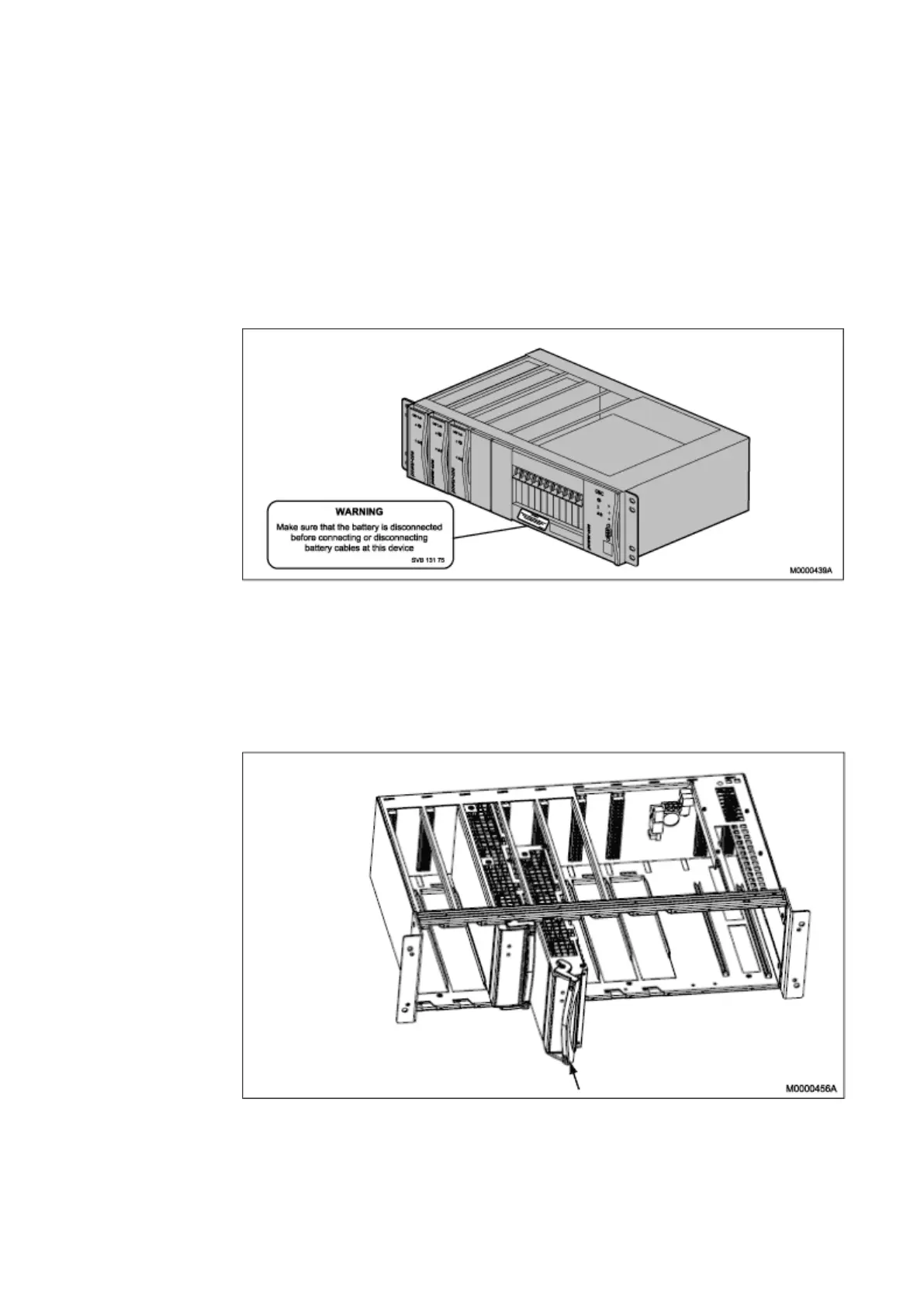
5. Fasten the warning label, energy hazard (SVB 131 75) below the circuit
breakers on the front of the AC/DC unit, Page 53 and Page 80
Figure 39 Energy Hazard Warning Label
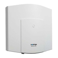
When adding a rectifier module (BML 351 054) always start from the left most
position in the subrack. Unscrew the lower and upper fixing screw and remove
the dummy front. Place the module into the correct mounting position and slide
carefully the module until it contacts the interface connection at the rear of the
shelf see Figure 35. When the rectifier reaches the backplane, push in the
handle and use the lower and upper fixing screw to fasten the module.
Figure 40 Adding a Rectifier Module
53
6/1531-ASP 113 01 Uen J2 2008-07-17