25
2600T SERIES | PRESSURE TRANSMITTERS | OI/266/FF-EN REV. E
Installation recommendations
Impulse piping configuration depends on the specific
measurement application.
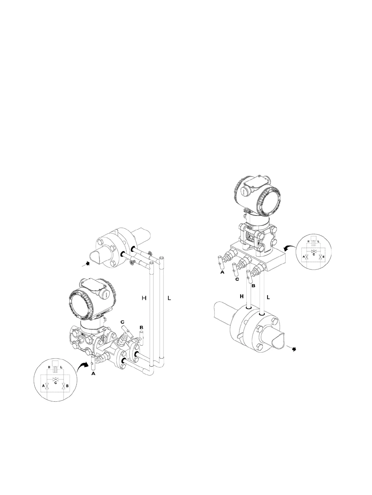
Steam (condensable vapor) or clean liquids flow measurement
• Place taps to the side of the line.
• Mount beside or below the taps.
• Mount the drain/vent valve upward.
• In case of steam application fill the vertical section of the
connecting lines with a compatible fluid through the filling tees.
The process fluid must enter the transmitter primary:
1 Open equalizing valve (C)
2 Close low pressure (B) and high pressure (A) valves .
3 Open gate valves
4 Slowly open high pressure (A) valve to admit process fluid to
both sides of primary.
5 Vent or drain the primary unit and then close the valves.
6 Open the (B) valve and close the equalizing valve.
Figu re 28: Steam or clean liquid flow measurement (transmitter and manifold)
Gas or liquid (with solids in suspension) flow measurement
• Place the taps to the top or side of the line.
• Mount the transmitter above the taps.
The process fluid must enter the transmitter primary:
1 Open equalizing valve (C)
2 Close low pressure (B) and high pressure (A) valves .
3 Open gate valves
4 Slowly open high pressure (A) valve to admit process fluid to
both sides of primary.
5 Vent or drain the primary unit and then close the valves.
6 Open the (B) valve and close the equalizing valve.
Figure 29: Gas or liquid flow measurement (transmitter and manifold)

 Loading...


