30
2600T SERIES | PRESSURE TRANSMITTERS | OI/266/FF-EN REV. E
7 Transmitter wiring
WARNING - GENERAL RISK
Observe the applicable regulations governing electrical
installation. Connections must only be established in a
dead-voltage state. Since the transmitter has no switch-off
elements, overvoltage protection devices, lightning
protection, and voltage separation capacity must be
provided at the plant (overvoltage/lightning protection is
optional). Check that the existing operating voltage
corresponds to the voltage indicated on the name plate. The
same lines are used for both the power supply and output
signal. In case the surge protection option is present and
the transmitter is installed in a Hazardous area, the
transmitter has to be power supplied from a voltage source
isolated from mains (galvanic separation). Furthermore the
potential equalization for the entire powering cable must be
guaranteed since the intrinsic safety circuit of the
transmitter is grounded.
WARNING - GENERAL RISK
Electrical shock can result in death or serious injury. Avoid
contact with the leads and terminals. High voltage that may
be present on leads can cause electrical shock.
WARNING - GENERAL RISK
Do NOT make electrical connections unless the electrical
code designation stamped on the transmitter data plate
agrees with the classification of the area in which the
transmitter is to be installed. Failure to comply with this
warning can result in fire or explosion.
Cable connection
Depending on the design supplied, the electrical connection is
established via a cable entry, M20 x 1.5 or 1/2-14 NPT thread, or
Han 8D plug (8U) (PROFIBUS PA and FOUNDATION Fieldbus: M12
x 1 or 7/8 plug). The screw terminals are suitable for wire cross
sections of up to 2.5 mm2 (AWG 14).
IMPORTANT
With Category 3 transmitters for use in “Zone 2”, a qualified
cable gland for this type of protection must be installed by
the customer (see the section “Hazardous Area Consideration”).
An M20 x 1.5 threads is located in the electronics housing
for this purpose.
For transmitters with “Flameproof enclosure” (Ex d) type of
protection, the housing cover must be secured using the
locking screw.
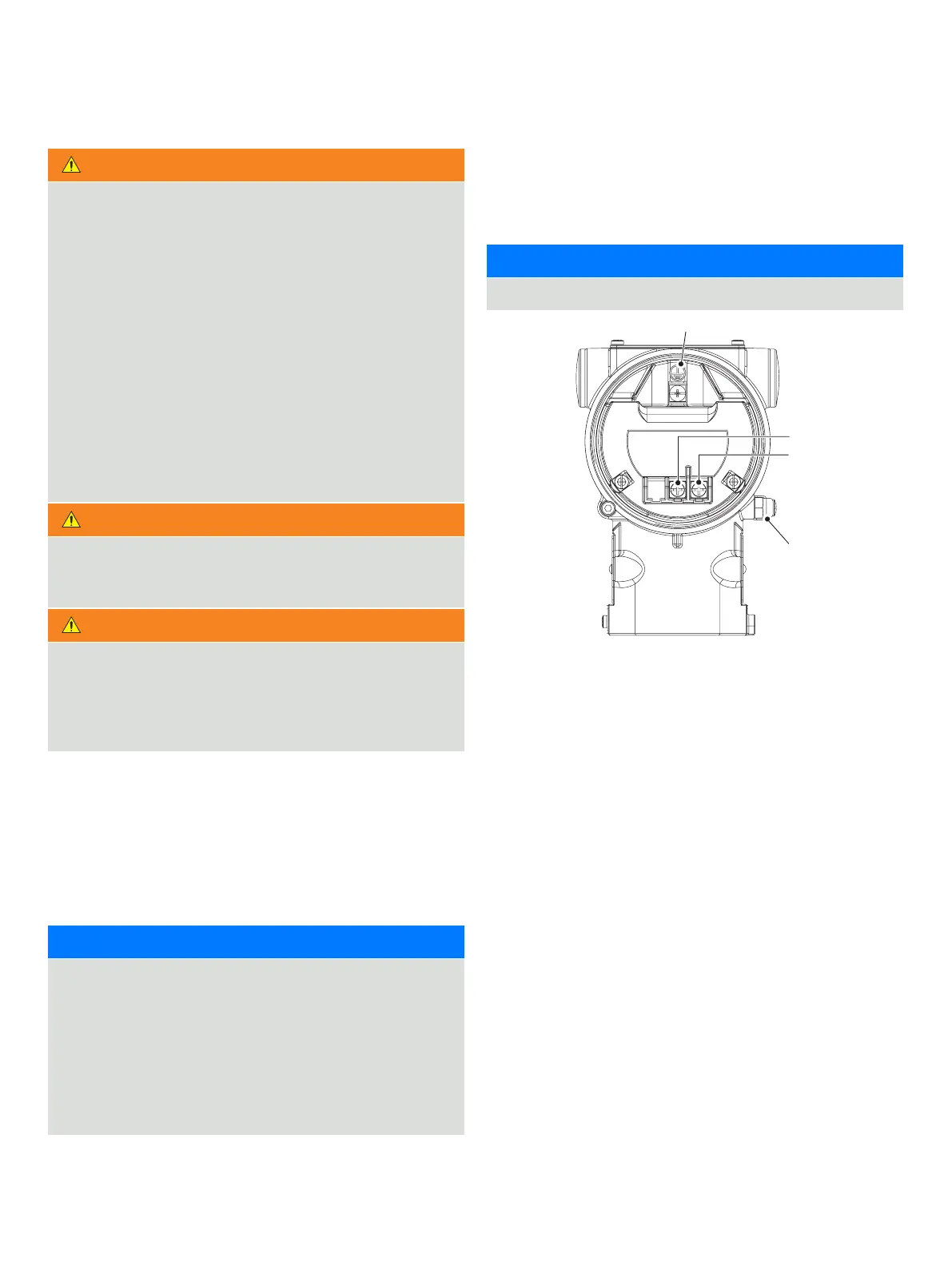
FOUNDATION Fieldbus wiring
The 2600T-266 PdP FF is a Bus Powered device with Fieldbus
Foundation output. The two wires of the bus have to be
connected as in the picture.
IMPORTANT
The 266 PdP FF is not Polarity Sensitive.
Figure 38: Device function block application

 Loading...


