12
2600T SERIES | PRESSURE TRANSMITTERS | OI/266/FF-EN REV. E
Pressure Equipment Directive (PED)
(2014/68/EU)
Devices with PS > 200 bar
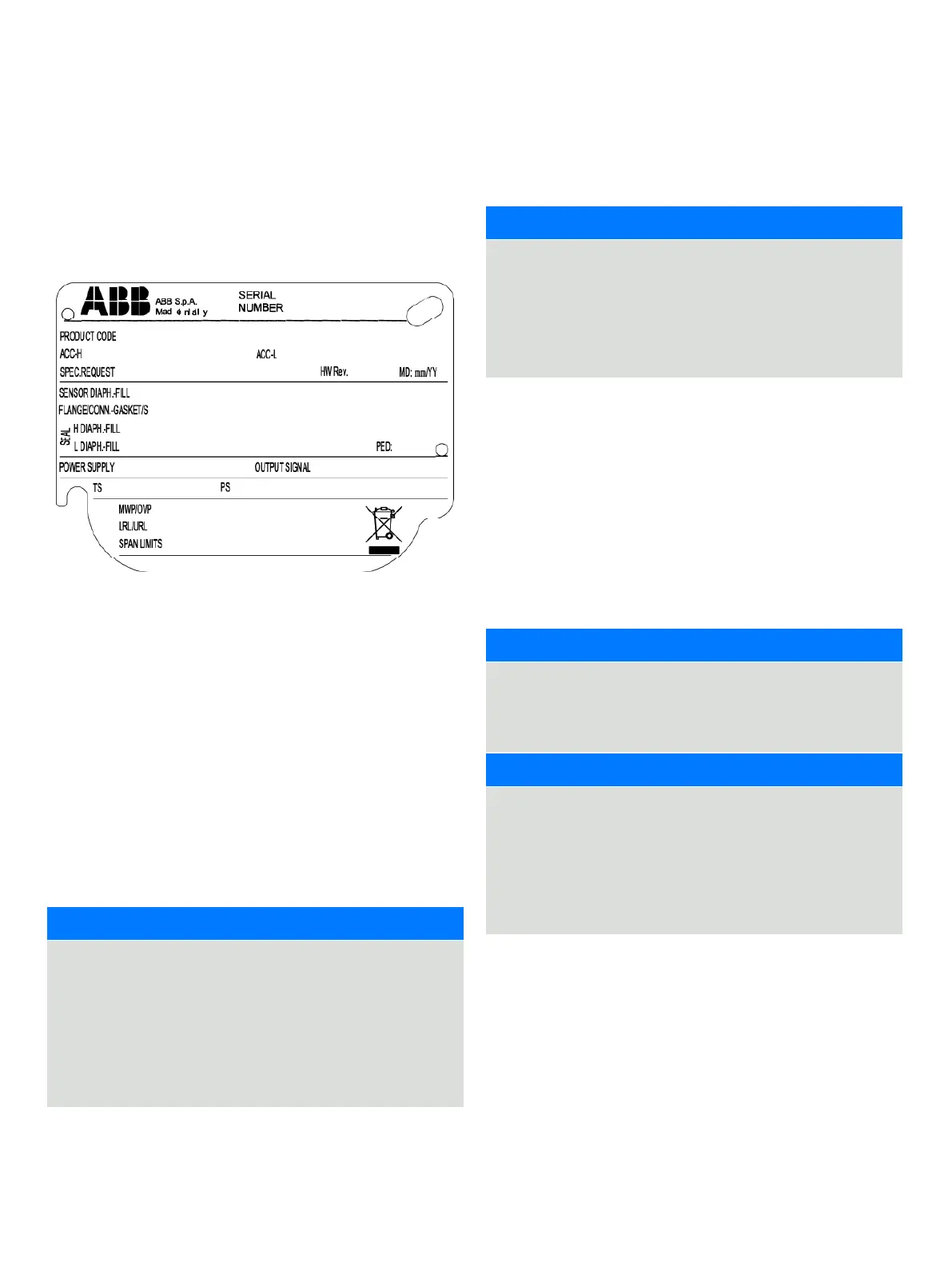
Devices with a permissible pressure PS >200 bar have been
subject to a conformity validation. The data label includes the
following specifications:
Figure 5: 266 nameplate with PED data
Devices with PS ≤200 bar
Devices with a permissible pressure PS ≤200 bar correspond to
article 3 paragraph (3). They have not been subject to a
conformity validation. These instruments were designed and
manufactured acc. to SEP Sound Engineering Practices.
Mounting a DP sensor transmitter
The pressure transmitter models 266DSH, 266MST and 266RST
can be mounted directly on the manifold. A mounting bracket
for wall or pipe mounting (2” pipe) is also available as an
accessory. For models 266DRH, 266MRT and 266RRT always
mounting brackets should be used. Ideally, the pressure
transmitter should be mounted in a vertical position to prevent
subsequent zero shifts.
IMPORTANT
If the transmitter is installed inclined with respect to the
vertical, the filling liquid exerts hydrostatic pressure on the
measuring diaphragm, resulting in a zero shift. In such an
event, the zero point can be corrected via the zero push-
button or via the “set PV to zero” command. Please refer to
the following paragraph for further details. For transmitters
without diaphragm seals, please read the considerations on
the Vent/Drain.
During installation of the transmitter, zero shifts caused by
mounting (e.g., a slightly oblique mounting position due to a
remote seal, etc.) may occur; these must be corrected.
IMPORTANT
The transmitter must have reached its operating
temperature (approx. 5 min. after startup, if the transmitter
has already reached the ambient temperature).
This correction can be executed only if the Calibration
Lower Range value is 0.0 and must be made with process
(dp or p) = 0.
The correction consists in the Zero elevation/suppression
operation and can be done in two ways:
1 Locally by acting on the Z push button when the electronic
switch SW 3 is set to 0,
2 From remote station via FF communication writing 0.0 in the
PTRB_DESIRED_PRIMARY_VALUE
In case the Calibration Lower Range value is not 0.0 then the
correction cannot be made with the local Z push button, but it
can be done only from remote station via FF communication
writing the correct measure value in the PTRB_DESIRED_
PRIMARY_VALUE
IMPORTANT
After the above operations the Calibration Range Values are
not changed. The desired process output value is produced
through an internal calculation by applying an offset at the
measured value.
NOTICE
In case of a High Static differential pressure transmitter
(266DSH.x.H) please always open the equalization valve of
the manifold (if installed) before applying pressure to the
transmitter. High Static pressure can damage the sensor
causing a zero shift and a serious decrease of the total
performance in terms of accuracy. In this case, please
perform a full sensor trim.
It is important to mount the transmitter and to lay the process
piping so that gas bubbles, when measuring liquids, or
condensate when measuring gases, will flow back to the
process and not enter the transmitter measuring chamber.
Optional Vent/drain valves (code V1/V2/V3) on the transmitter
are located on the sensor flanges.
The transmitter has to be positioned so that these drain/vent
valves will be located higher than the taps on liquid service in
order to allow the venting of entrapped gas or below the taps
on gas service in order to allow the air to vent off or condensate
to drain off.

 Loading...


