The ACS800-37
29
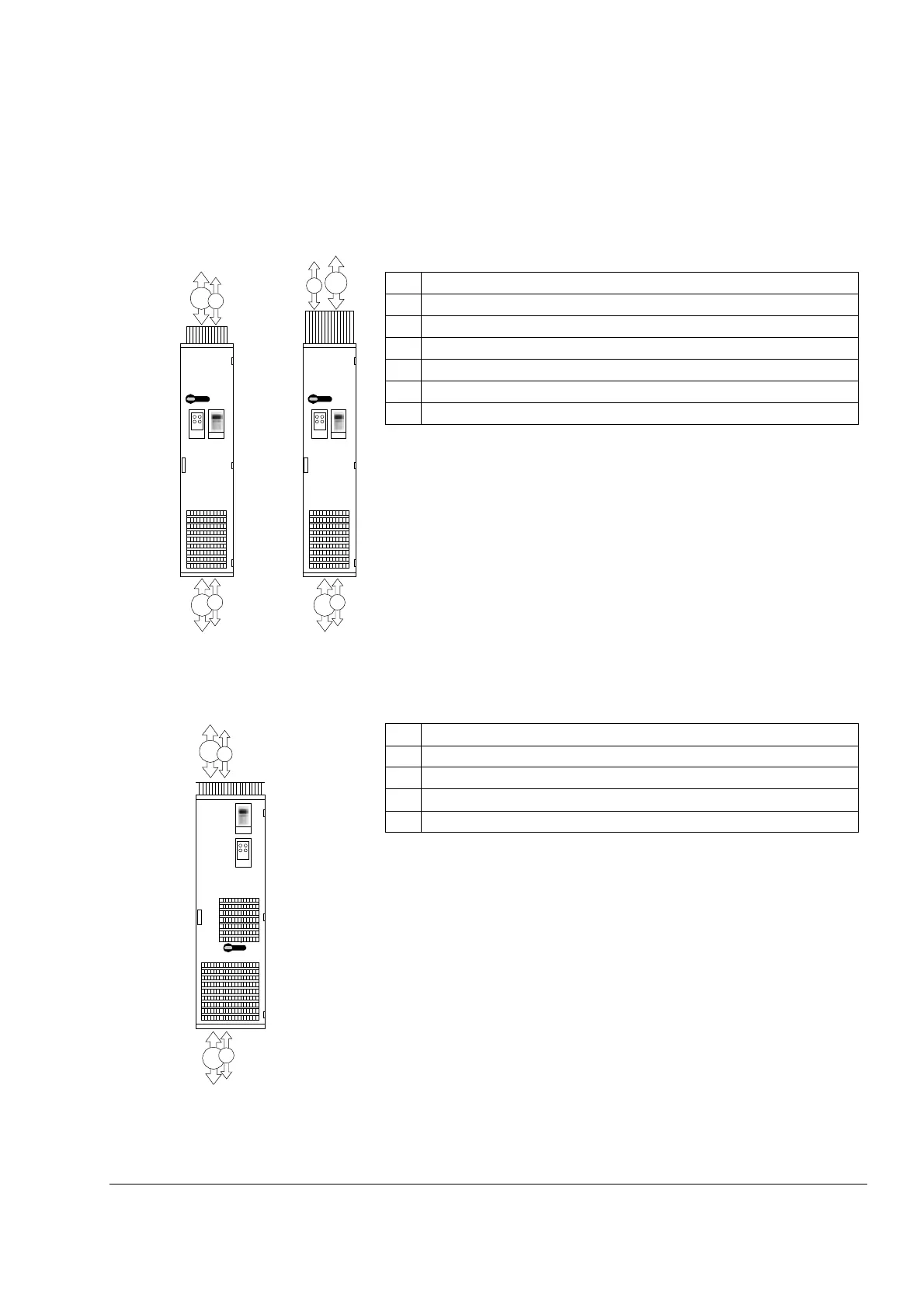
Cabling direction
The drawing below shows the available power cabling directions of the drive.
Description
1 Input/Motor output – Bottom entry
2 Input/Motor output – Top entry (IP21-42)
3 Input/Motor output – Top entry (IP54)
4 Signal cable input/output – Bottom entry
5 Signal cable input/output – Top entry (IP21-42)
6 Signal cable input/output – Top entry (IP54)
1
6
Frame size R6
4
2
5
3
1
4
IP54IP21-42
Description
1 Input/Motor output – Bottom entry
2 Input/Motor output – Top entry
3 Signal cable input/output – Bottom entry
4 Signal cable input/output – Top entry
Frame size R7i
1
3
2
4
 Loading...


