Electrical installation
79
Input power connection – Frame size R8i
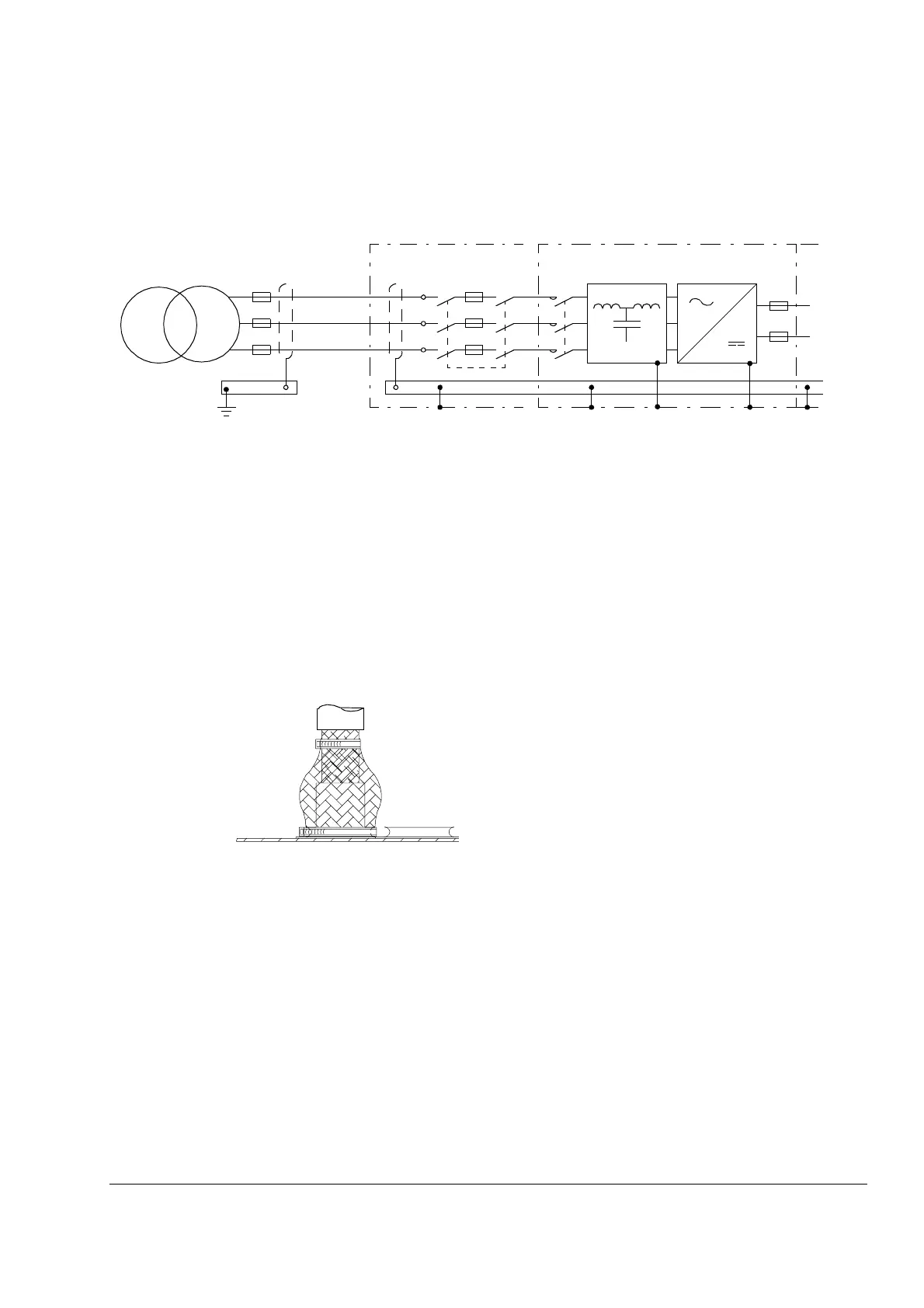
Connection diagram
Connection procedure
Note: Before making the cable connections, check that the tap settings of the
auxiliary voltage transformer (T10, located in the input/output cubicle) are correct in
regard to the supply voltage. See instructions on page 94.
1. Open the door of the input/output cubicle (see section Cabling direction starting on
page 29).
2. Remove any shrouds that protect the input busbars and cable entries.
3. Lead the cables into the inside of the cubicle. It is recommended to apply 360°
grounding of the cable shields at the entry as shown below.
4. Connect the cables as follows:
• Twist the cable shields into bundles and connect to cabinet PE (ground) busbar.
Connect any separate ground conductors or cables to cabinet PE (ground)
busbar.
• Connect the phase conductors to the input power terminals (L1, L2, L3). For the
tightening torques, see the chapter Technical data.
5. Provide support for the cables whenever necessary.
6. Refit all shrouds removed earlier and close the door.
Q1
PE
L1
L2
L3
K1 L1 U1
 Loading...


