Electrical installation
82
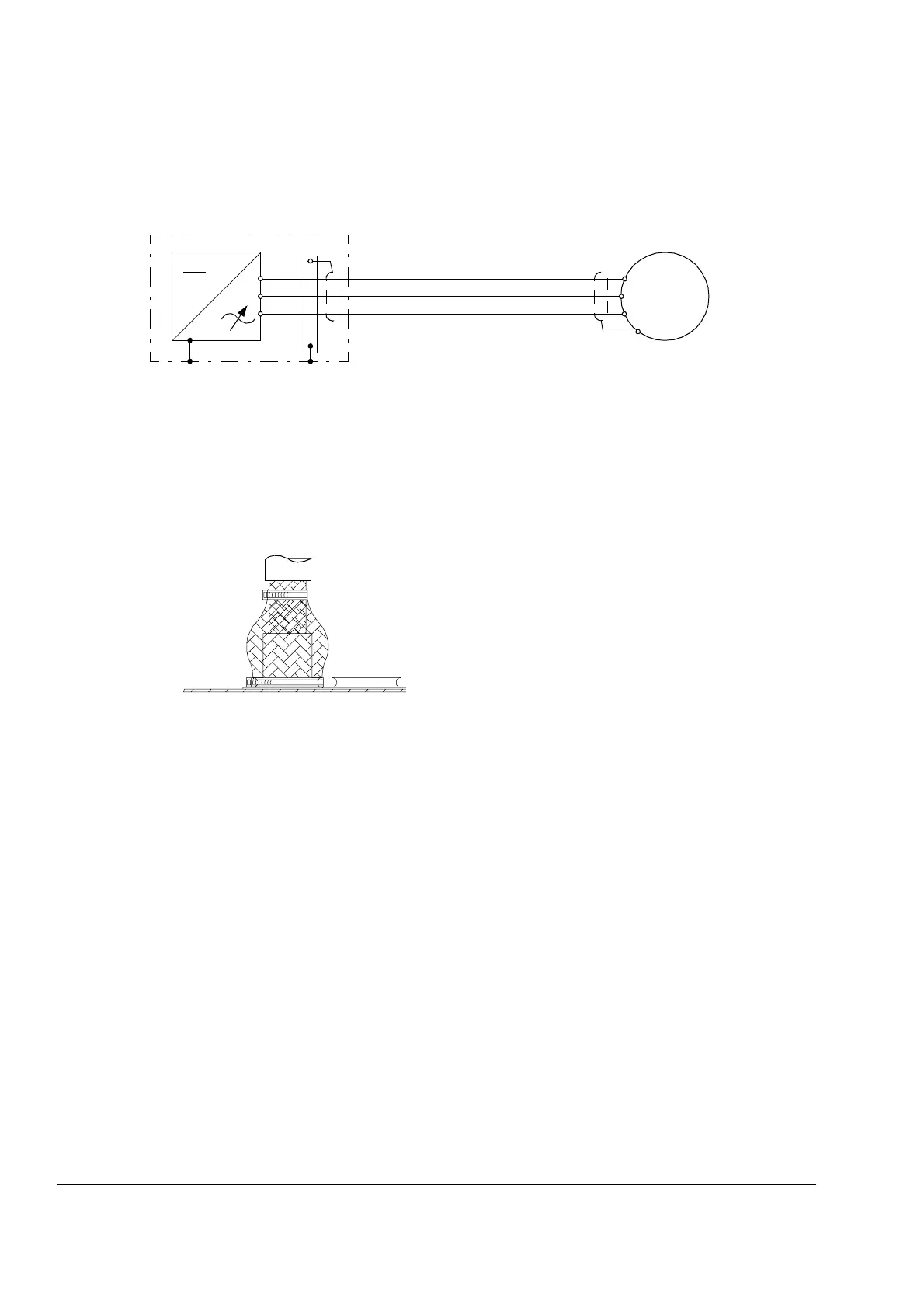
Motor connection – Frame R7i
Connection diagram
Connection procedure
1. Open the cabinet door.
2. Remove any shrouds that protect the output busbars and cable entries.
3. Lead the cables into the inside of the cubicle. It is recommended to apply 360°
grounding of the cable shields at the entry as shown below.
4. Connect the cables as follows:
• Twist the cable shields into bundles and connect to cabinet PE (ground) busbar.
Connect any separate ground conductors or cables to cabinet PE (ground)
busbar.
• Connect the phase conductors to the output power terminals (U2, V2, W2). For
the tightening torques, see the chapter Technical data.
5. Provide support for the cables whenever necessary.
6. Refit all shrouds removed earlier and close the door.
U2
V2
W2
PE
M
3~
U1
W1
V1
PE
 Loading...


