Electrical installation
54
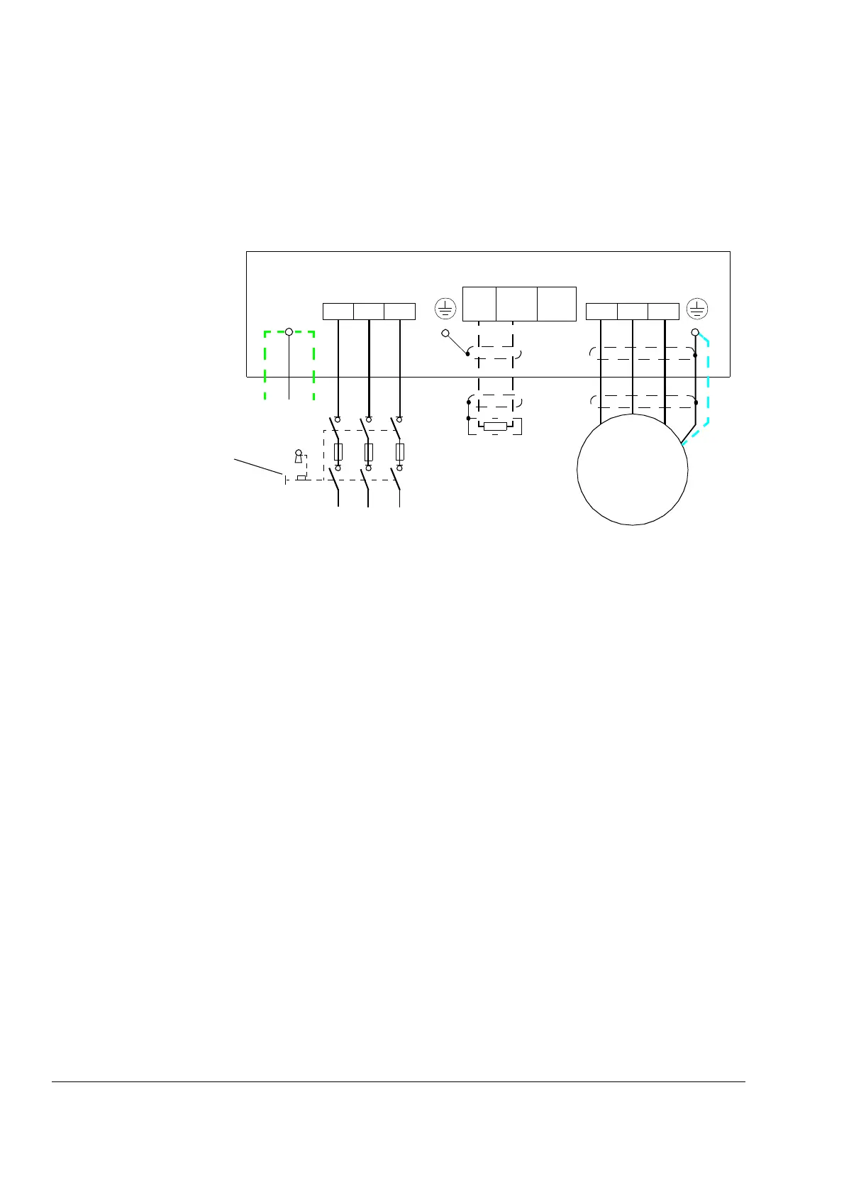
Power cable connection
Power cable connection diagram
Notes:
– If shielded supply (input) cable is used, and the conductivity of the shield is less than 50% of the conduc-
tivity of a phase conductor, use a cable with a ground conductor (1) or a separate PE cable (2). With
shielded cable, 360° grounding at cable entry is recommended.
– For motor cabling, use a separate ground cable (3) if the conductivity of the cable shield is less than 50%
of the conductivity of a phase conductor and the cable has no symmetrical ground conductors. See also
section Selecting the power cables on page 42.
If there is a symmetrically-constructed ground conductor in the motor cable in addition to the conductive
shield, connect it to the ground connectors at both the drive and motor ends. Do not use an asymmetri-
cally-constructed motor cable.
INPUT
OUTPUT
U1
V1
W1
3
~
Motor
U1
1)
UDC+
R+
UDC-
R-
L1 L2 L3
(PE) (PE)PE
2)
3)
PE
For alternatives, see
Planning the electrical
installation: Supply
disconnecting device.
Optional braking
resistor (360°
grounding required)
ACSM1-04
V1 W1 U2 V2 W2
PE

 Loading...


