Electrical installation
58
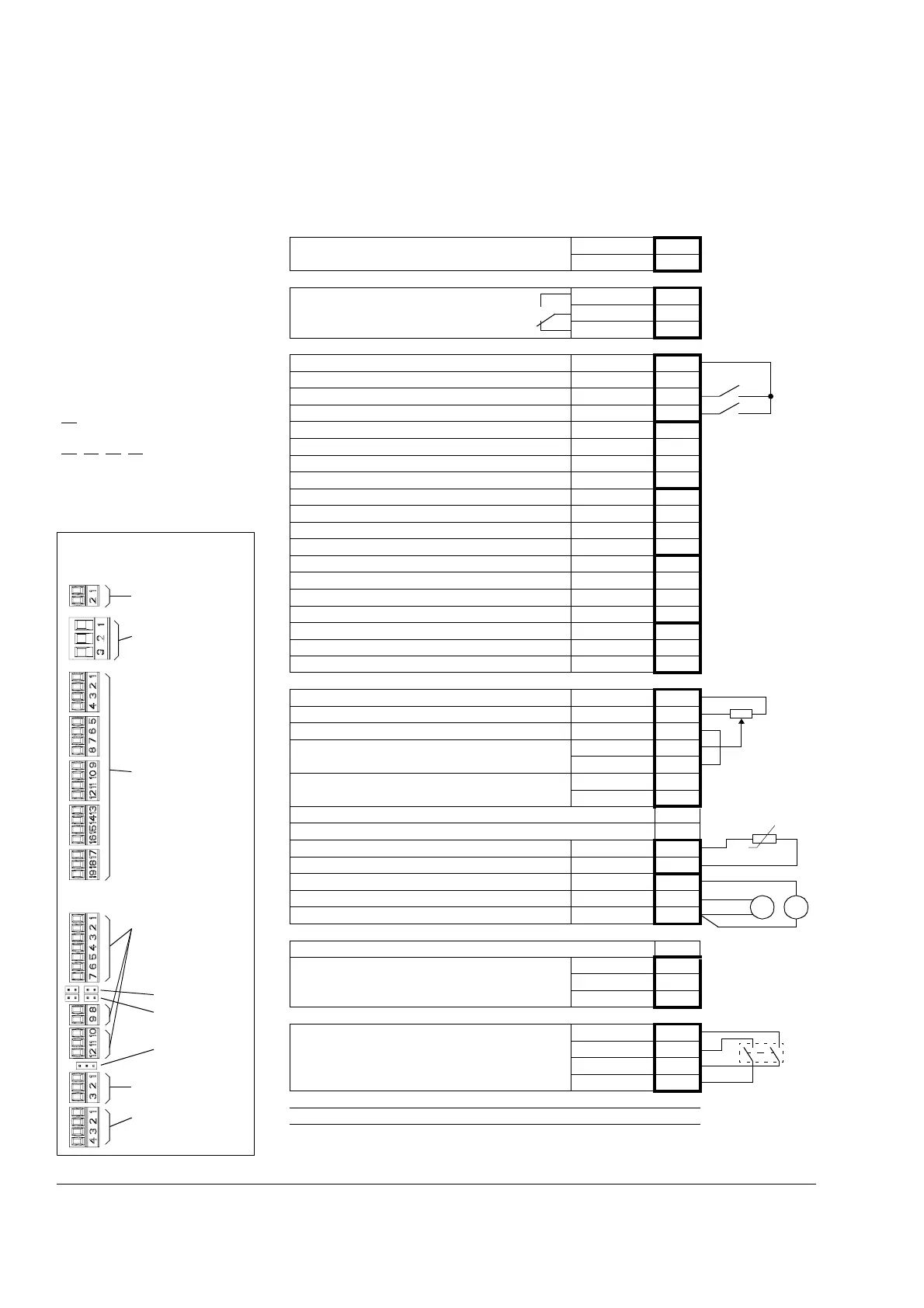
Connecting the control cables
Control connections to the JCU Control Unit
Notes:
[Default setting]
*Total maximum current: 200 mA
**Default assignment with ACSM1
Motion Control Program
The wiring shown is for demonstrative
purposes only. Further information of
the usage of the connectors and
jumpers are given in the text; see also
the chapter Technical data.
Wire sizes and tightening torques:
X2
: 0.5 … 2.5 mm
2
(24…12 AWG).
Torque: 0.5 N·m (5 lbf·in)
X3
, X4, X5, X6:
0.5 … 1.5 mm
2
(28…14 AWG).
Torque: 0.3 N·m (3 lbf·in)
X1
External power input
24 V DC, 1.6 A
+24VI 1
GND 2
X2
Relay output
250 V AC / 30 V DC
2 A
NO 1
COM 2
NC 3
X3
+24 V DC* +24VD 1
Digital I/O ground DGND 2
Digital input 1 [Stop/Start] DI1 3
Digital input 2 [EXT1/EXT2] DI2 4
+24 V DC* +24VD 5
Digital I/O ground DGND 6
Digital input 3 [Fault reset] DI3 7
Digital input 4 [Positioning start]** DI4 8
+24 V DC* +24VD 9
Digital I/O ground DGND 10
Digital input 5 [Position ref. set 1/2]** DI5 11
Digital input 6 [Homing start]** DI6 12
+24 V DC* +24VD 13
Digital I/O ground DGND 14
Digital input/output 1 [Ready] DIO1 15
Digital input/output 2 [Running] DIO2 16
+24 V DC* +24VD 17
Digital I/O ground DGND 18
Digital input/output 3 [Fault] DIO3 19
X4
Reference voltage (+) +VREF 1
Reference voltage (–) -VREF 2
Ground AGND 3
Analogue input 1 (Current or voltage, selectable
by jumper J1) [Speed reference]
AI1+ 4
AI1- 5
Analogue input 2 (Current or voltage, selectable
by jumper J2) [Torque reference]
AI2+ 6
AI2- 7
AI1 current/voltage selection J1
AI2 current/voltage selection J2
Thermistor input TH 8
Ground AGND 9
Analogue output 1 (current) [Output current] AO1 (I) 10
Analogue output 2 (voltage) [Actual speed] AO2 (U) 11
Ground AGND 12
X5
Drive-to-drive link termination J3
Drive-to-drive link.
B1
A2
BGND 3
X6
Safe Torque Off. Both circuits must be closed for
the drive to start.
OUT1 1
OUT2 2
IN1 3
IN2 4
Control panel connection X7
Memory unit connection X205
X3 (4 × 4-pole,
1 × 3-pole)
X2 (3-pole)
X1 (2-pole)
X4 (1 × 7-pole,
1 × 2-pole,
1 × 3-pole)
X5 (3-pole)
X6 (4-pole,
orange)
J1
J3
J2
Order of terminal headers and
jumpers
T

 Loading...


