Single and dual input analyzers for pH/Redox (ORP)
AX416, AX436, AX460, AX466 & AX468 6Installation
IM/AX4PH Rev. P 49
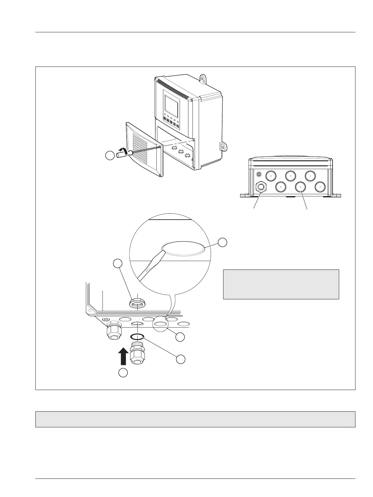
6.3.2 Cable Entry Knockouts, Wall-/Pipe-mount Analyzer
The analyzer is supplied with 7 cable glands, one fitted and six to be fitted, as required, by the user – see Fig. 6.7.
Fig. 6.7 Cable Entry Knockouts, Wall-/Pipe-mount Analyzer
Note. The cable glands must be tightened to a torque of 3.75 Nm (33 lbf. in.)
5
Place the blade of a small, flat bladed screwdriver
into the knockout groove and tap the
screwdriver smartly to remove the knockout
(see Note below)
Smooth the edges of the hole
with a small round or half-round file
Fit an 'O' ring seal to the the cable gland
Insert the cable gland into the hole in the analyzer case from the outside.
Tighten the gland to a torque of 3.75 Nm (33 lbf. in.)
Secure the cable
gland with the nut
2
3
4
6
Cable entry knockouts
Factory-fitted cable gland
1
Release the four captive
screws and remove
the terminal cover plate
Note. When removing knockouts, take
great care not to damage wiring and
components within the analyzer.

 Loading...


