Single and dual input analyzers for pH/Redox (ORP)
AX416, AX436, AX460, AX466 & AX468 2 Operation
IM/AX4PH Rev. P 3
2 Operation
2.1 Powering Up the Analyzer
1. Ensure the input sensors are connected correctly.
2. Switch on the power supply to the analyzer. A start-up
screen is displayed while internal checks are performed,
then the Operating Page (Section 2.3) is displayed as the
pH or Redox (ORP) monitoring operation starts.
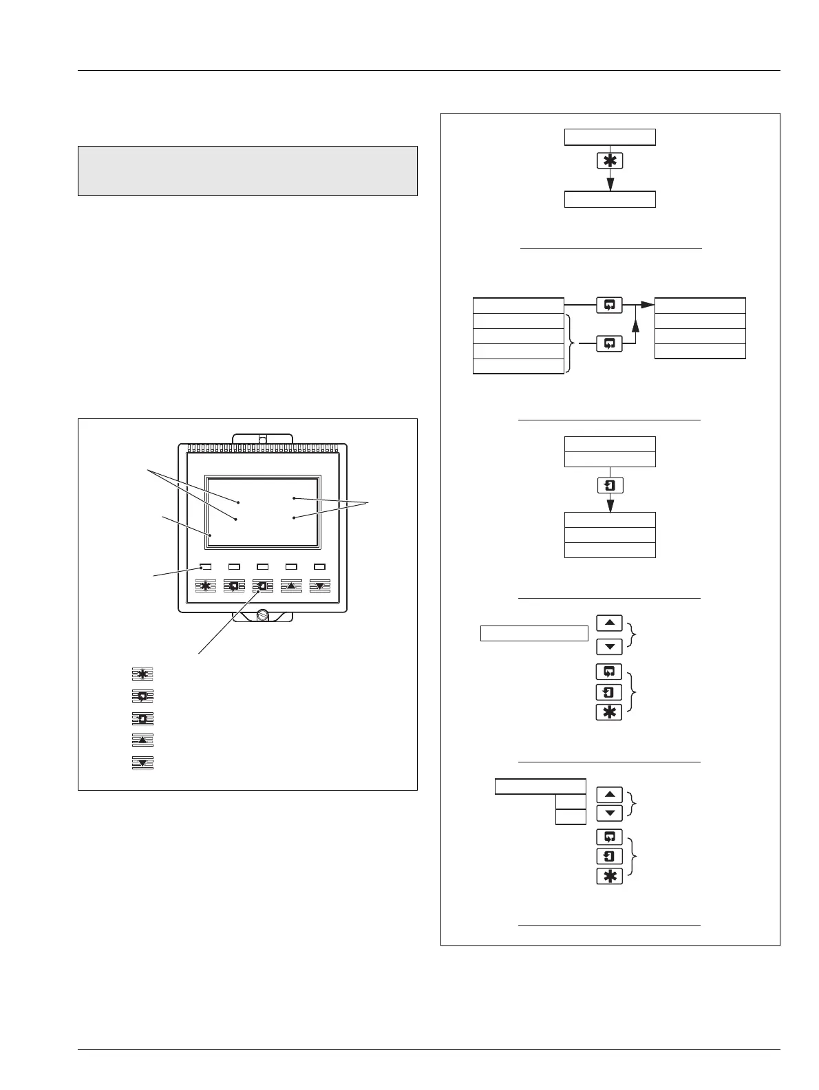
2.2 Displays and Controls
The display comprises two rows of 4
1
/2 digit, 7-segment digital
displays, that show the actual values of the measured
parameters and alarm set points, and a 6-character dot matrix
display showing the associated units. The lower display line is a
16-character dot matrix display showing operating and
programming information.
2.2.1 Membrane Key Functions
Warning. Ensure all connections are made correctly,
especially to the earth stud – see Section 6.3, page 47.
Fig. 2.1 Location of Controls and Displays
0.00
Monitoring pH
0.00
Alarm
LEDs
Display
Lines
Lower
Display Line
Membrane Keys
pH
Units
Menu Key
Sidescroll Key
Downscroll Key
Up Key
Down Key
pH
Fig. 2.2 Membrane Key Functions
B Advancing to Next Page
C Moving Between Frames
D Adjusting and Storing a Parameter Value
E Selecting and Storing a Parameter Choice
A Moving Between Menus
For majority
of Frames
Frame 1
Frame 2
Frame 3
Frame 4
Page 1
Frame 1
Frame 2
Frame 3
Page 2
Advance to
next page
or
Frame 1
Frame 2
Frame 3
Page X
Frame 4
Advance to
next Frame
New value is
stored automatically
Parameter Value
Adjust
Parameter X
Y
Z
Select
New value is
automatically stored
Menu 1
Menu 2
Advance to
next menu

 Loading...


