Single and dual input analyzers for pH/Redox (ORP)
AX416, AX436, AX460, AX466 & AX468 6Installation
IM/AX4PH Rev. P 53
6.5.2 Connections
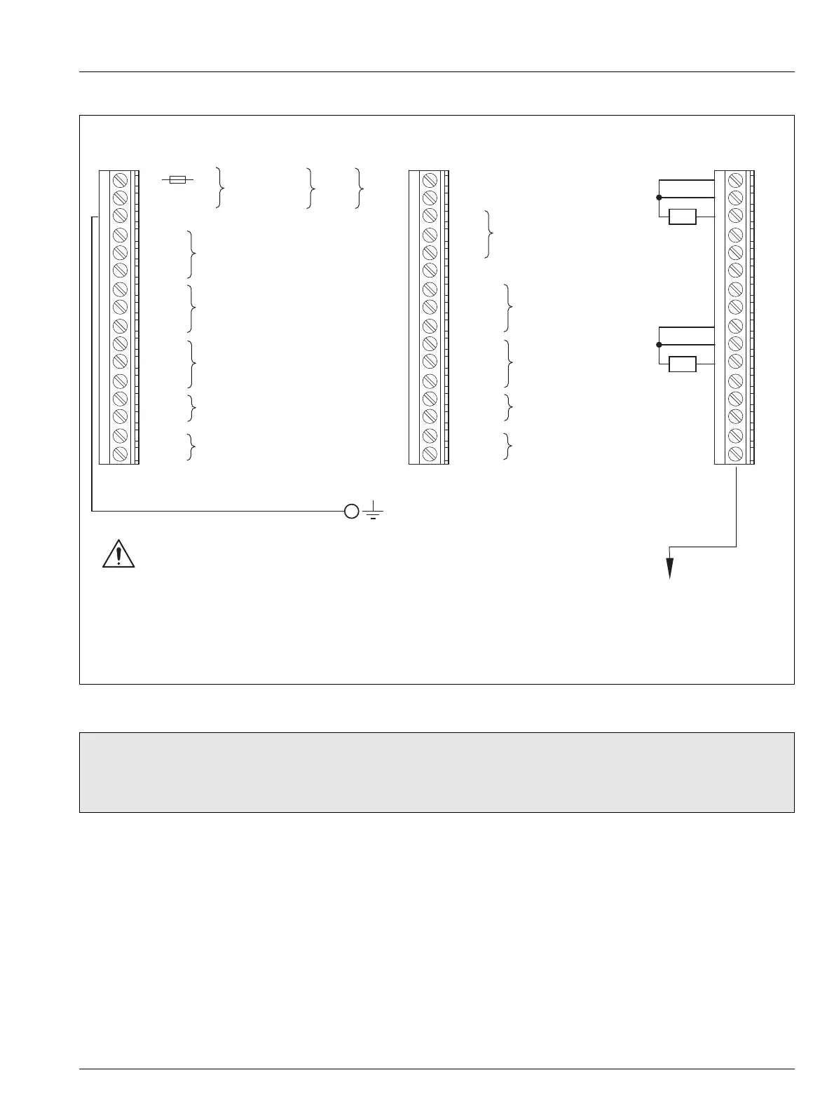
Fig. 6.11 Connections, Panel-mount Analyzers
Note.
Relay 3 can be configured to control the wash facility – see Section 5.4, page 33.
Tighten the terminal screws to a torque of 0.60 Nm (5.3 lbf. in.).
L Line
N Neutral
E Connect supply earth (ground) to stud on case
A4 C
A5
NC
Relay 1
A6 NO
A7 C
A8 NC Relay 2
A9 NO
A10 C
A11 NC Relay 3 (see NNNN below)
A12 NO
A13 +
Analog Output 1
A14 —
A15 +
Analog Output 2
A16 —
Terminal Block BTerminal block A
Temperature Compensator
Connections
Common
Third Lead
TC
B1
B2
B3
B4
B5
B6
B7
B8
B9
B10
B11
B12
B13
B14
B15
B16
Common
Third Lead
TC
Temperature Compensator
Connections
Terminal Block C
(Option Board)
C1 Not Used
C2 Not Used
C3
C4
C5
C6 Not Used
C7 C
C8 NC Relay 4
C9 NO
C10 C
C11 NC Relay 5
C12 NO
C13 +
Analog Output 3
C14 —
C15 +
Analog Output 4
C16 —
Earth (Ground)
Stud on Case
(see Fig. 6.10)
PROFIBUS DP
connections –
refer to IM/PROBUS
+12
100 to 240 V AC to
Power
– 30V DC
Supplies
Before making any electrical connections,
see Warnings on page 47
*
* 250 mA Type T fues (mains AC) or
2 A Type T fuse (DC)
**
**
**
Refer to Section 6.6 for pH Sensor System
Connection Details
** Ensure polarity is correct before
switching power supply on.

 Loading...


