Single and dual input analyzers for pH/Redox (ORP)
AX416, AX436, AX460, AX466 & AX468 8 Simple Fault Finding
62 IM/AX4PH Rev. P
8 Simple Fault Finding
8.1 Error Messages
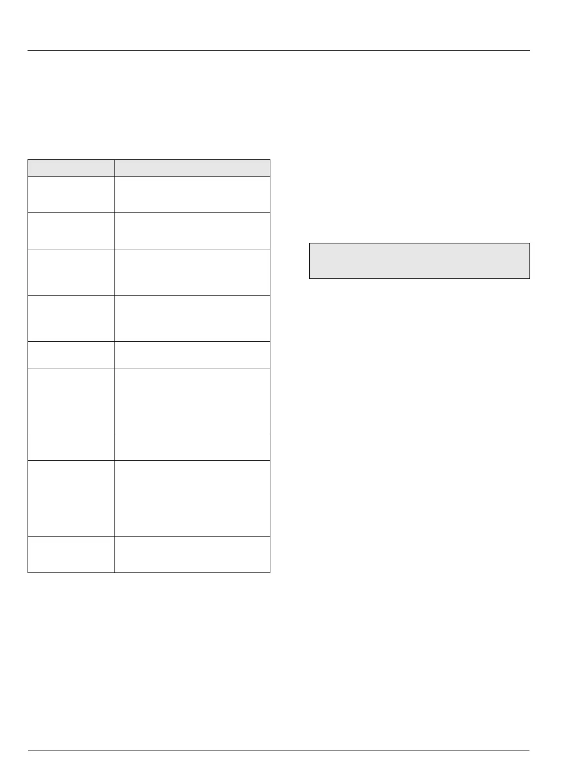
If erroneous or unexpected results are obtained, the fault may
be indicated in the Operating Page by an error message – see
Table 8.1. However, some faults may cause problems with
analyzer calibration or give discrepancies when compared with
independent laboratory measurements.
8.2 Calibration Fail Message or No Response to
pH/Redox Changes
The majority of problems are associated with the electrodes and
cabling. Replace the electrodes as an initial check – refer to the
appropriate instruction manual. It is also important that all
program parameters have been entered correctly and have not
been altered inadvertently – see Section 7, page 56.
If the above checks do not resolve the fault:
1. Check that the analyzer responds to a millivolt input.
Connect a pH simulator, such as Model 2410, to the
transmitter input; +ve to glass and –ve to reference – see
Section 6.4, page 50 or 6.5. Select the
CONFIG. SENSORS
page and set the Probe Type to Redox or ORP. Check that
the analyzer displays the correct values as set on the
simulator.
Failure to respond to the input indicates a fault with the
analyzer which must be returned to the Company for
repair. Correct response, but with incorrect readings,
usually indicates a calibration problem. Recalibrate the
analyzer as detailed in Section 7.
2. Use the pH simulator to carry out an impedance check on
the analyzer, i.e. glass to reference, glass to earth and
reference to earth – refer to simulator manual.
If the analyzer fails this test, check for moisture within the
transmitter and in particular the terminal compartment. It is
vital that all evidence of moisture is removed with the use
of a hot air drier.
3. Reconnect the electrode cable and connect the simulator
to the electrode end of the cable. Repeat the procedures
1) and 2) above. If the analyzer fails test 2), check for
moisture around the connections and check that the
insulation on the inner co-axial conductor is clean and that
the graphite layer has been removed.
Error Message Possible Cause
A: FAULTY Pt100
A: FAULTY Pt1000
A: FAULTY BALCO
Temperature compensator/associated
connections for Sensor A are either open
circuit or short circuit.
B: FAULTY Pt100
B: FAULTY Pt1000
B: FAULTY BALCO
Temperature compensator/associated
connections for Sensor B are either open
circuit or short circuit.
A: CAL LOW SLOPE
B: CAL LOW SLOPE
Although the calibration has not failed, the
electrode pair associated with the sensor
indicated is becoming fatigued and
replacement is recommended.
A: PH CAL FAILED
B: PH CAL FAILED
The calibration of the sensor indicated has
failed. Check buffer values and repeat
buffering. If the fault persists, replace the
electrodes.
WASH INHIBITED
Wash Function is set to Off. Set Wash
Function
to On – see Section 2.3.3, page 8.
A: OUT OF SAMPLE
A: BROKEN CABLE
(alternating display)
B: OUT OF SAMPLE
B: BROKEN CABLE
(alternating display)
1. The sensor indicated is not fully immersed
in sample.
2.The cable associated with the sensor
indicated may be damaged.
A: BROKEN CABLE
B: BROKEN CABLE
The cable associated with the sensor
indicated may be damaged.
A: LOW GLASS IMP.
A: BROKEN CABLE
(alternating display)
B: LOW GLASS IMP.
B: BROKEN CABLE
(alternating display)
1. The glass electrode associated with the
sensor indicated may be broken.
2.The cable associated with the sensor
indicated may be damaged.
3.The connections associated with the
sensor indicated may be faulty.
A: CHECK REF.
B: CHECK REF.
The reference electrode associated with the
sensor indicated may need cleaning or the
sensor may need replacing.
Table 8.1 Error Messages
Note. A normal laboratory mV source is not suitable
for use as a pH simulator.

 Loading...


