EasyManuals Logo

ABB Cylon FBXi Series User Manual

ABB Cylon FBXi Series
82 pages
To Next Page IconTo Next Page
To Previous Page IconTo Previous Page
Page #38 background imageLoading...
Page #38 background image
FBXi Series | Installation
©ABB 2023 All Rights Reserved.
Subject to change without notice
WWW.CYLON.COM
38
5 Installation
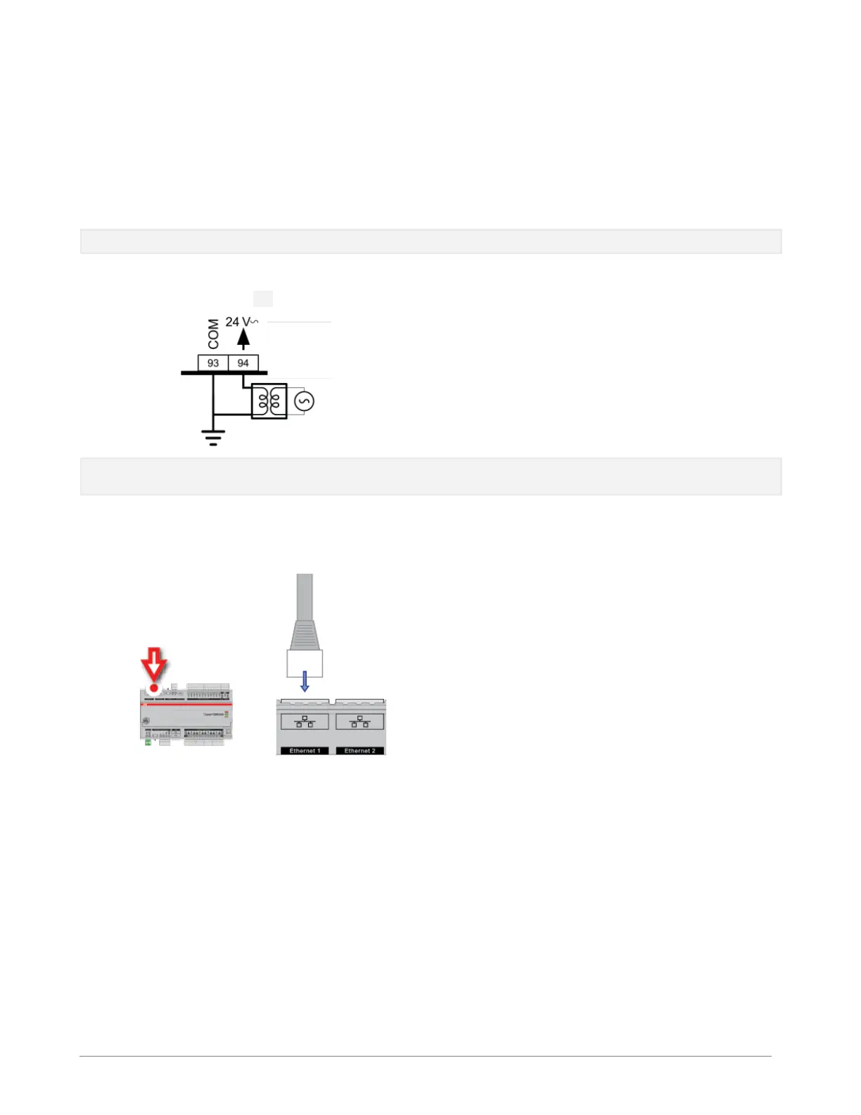
APPLY POWER TO THE FBXi
For the initial configuration of the device, the controller must first be powered on.
Note: Service Port (USB connection) must not be connected until after the device is powered on.
The FBXi-256 requires 24 V AC/DC supplied from an externally mounted power transformer. One conductor
of the transformer must be grounded to an earth ground to avoid damage to the controller. This conductor
will be wired to the COM (common) terminal of the controller. The wiring diagram is shown here:
Note: Ensure the 24 V AC/DC and Common wires are correctly connected to the controller. If the wires are
swapped, it may cause damage to anything connected to the controller.
CONNECT THE FBXi TO AN IP NETWORK
Place an Ethernet cable from the Network’s Ethernet switch into one of the 2 Ethernet ports on the top of the
FBXi:
IP Cabling requirements
Cable
Standard patch cable, Cat 5e with 4 pairs of wires fitted with RJ-45
connectors
RJ-45 pin connections
Straight-through wiring
Characteristic impedance
100-130 Ohms
Distributed capacitance
Less than 100 pF per meter (30 pF per foot)
Maximum Cable length
between IP devices
328 ft. (100 m) maximum

Table of Contents

Questions and Answers:

Question and Answer IconNeed help?

Do you have a question about the ABB Cylon FBXi Series and is the answer not in the manual?

ABB Cylon FBXi Series Specifications

General IconGeneral
BrandABB
ModelCylon FBXi Series
CategoryController
LanguageEnglish

Related product manuals