FBXi Series | FBXi Operation
©ABB 2023 All Rights Reserved.
Subject to change without notice
WWW.CYLON.COM
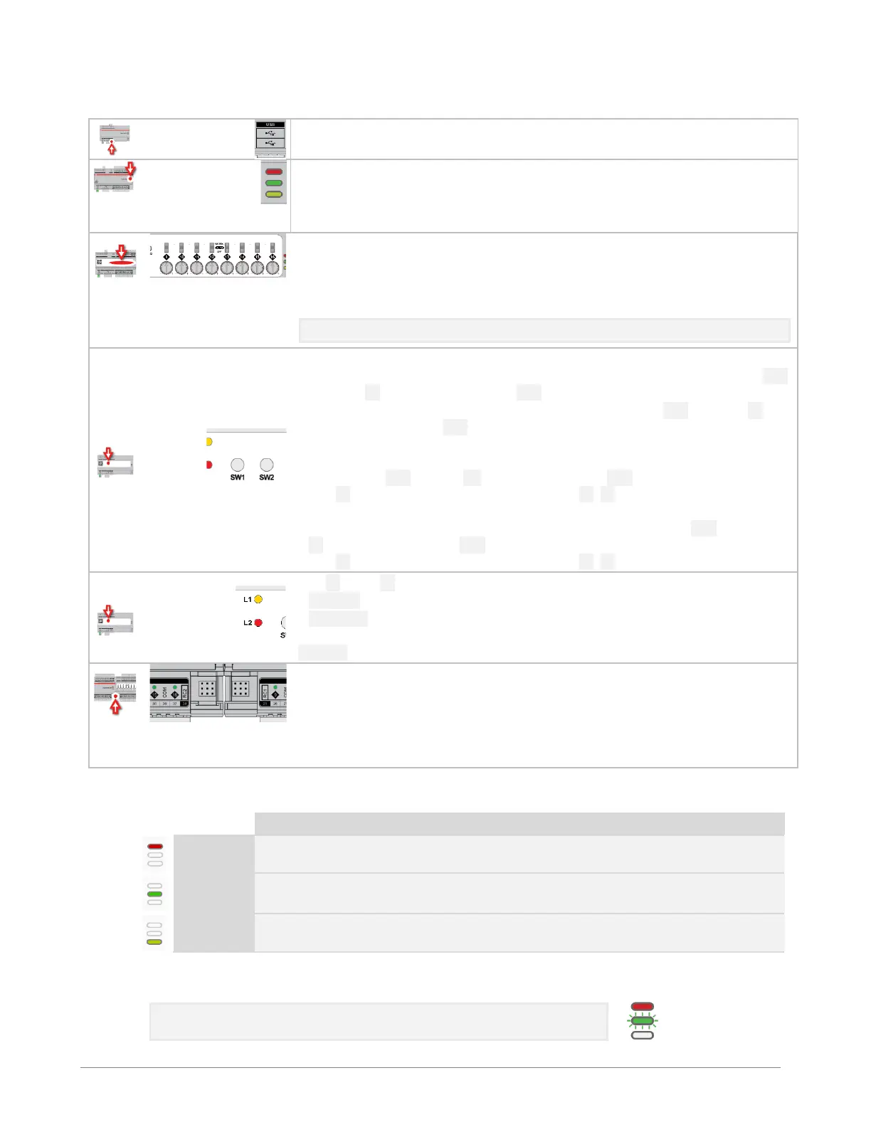
USB ports
Used for firmware upgrade
Indicator LEDs
(for LED signals see
FBXi Indicator LED Signals
on page 73)
Output Override (FBXi-8R8-H-X96 only)
Bottom position: Off - outputs forced off.
Centre position: Auto - outputs are controlled by strategy.
Top position: Manual - for digital outputs, the output is forced on. For analog
outputs the knob setting controls the output value.
Note: Manual position is supervised, i.e. the strategy is aware of the manual value.
Push buttons
Reset to Factory default IP/Password : while the controller is
running
, press SW1
until LED L2 lights up, then release SW1.
Restart the controller: while the controller is
running
, press SW2 until LED L2
lights up, then release SW2.
Factory Reset
(Reset to default Factory settings including, Shipped version of
firmware, wipe strategy data, and reset IP/Password):
while the controller is
booting
hold SW1 until LED L2 lights up, then release SW1.
LED L2 will indicate the progress as shown in L1 /L2 signals below.
USB upgrade: insert a FAT-formatted USB drive containing valid firmware (.swu)
into either of the USB ports, while the controller is
booting
hold SW1 until LED
L1 lights up, then release SW1.
LED L1 will indicate the progress as shown in L1 /L2 signals below.
LED L1 / LED L2 signals
Slow blink : Upgrade / Reset in progress
Solid colour: Upgrade / Reset successful.
Power-cycle the controller to activate.
Fast blink Upgrade /Reset failed
Inter-module connection sockets
To join the FLX bus, place the devices side-by-side and place the FLX bus
connector into the two adjacent sockets at once.
The end device on a FLX bus (either a FLX device or the CBXi itself) must have a
terminator inserted into its interconnector socket. One terminator is shipped
with each CBXi-8R8(-H) device.
FBXi INDICATOR LED SIGNALS
Strategy Loaded
but no network
connectivity
Strategy Loaded and
device communicating
on network
During firmware upgrade over IP network, the Yellow LED will remain on while the strategy/comms section
reboots, and then the LEDs will rotate Red-Green-Yellow while the IO section reboots.
Note: During typical operation, the Red LED should be on, the Green
LED should be blinking and the Yellow LED should be off.
 Loading...