Chapter 2 – Twelve–Pulse Technology
II F2
2 - 2 DCS 600 Manual for 12 – Pulse Operation
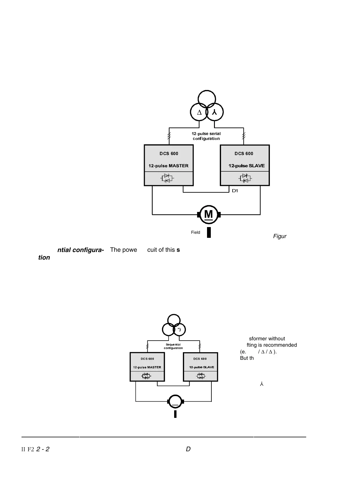
12 – pulse serial con-
figuration
In this 12 – pulse serial configuration the motor gets the sum of the
DC voltage of two converters. Thus the voltage is doubled.
An emergency operation is possible with full torque and with 50 % of
the former maximum armature voltage.
SXOVH6/$9(
C1D1
C1D1
∆
<
SXOVHVHULDO
FRQILJXUDWLRQ
Field
'&6 '&6
0
Figure 2/2
Sequential configura-
tion
The power circuit of this sequential configuration (Figure 2/3) is identi-
cal to that of the 12 – pulse serial configuration except that in most
cases the phase positions of the two transformer secondary windings
are identical (e.g. transformer configuration
∆ / ∆ / ∆ ). The motor gets
the sum of the DC voltage of two converters but both voltages are
normally not equal. This is the main difference to the 12-pulse opera-
tion mode. In consequence the motor must cope with a normal 6-pulse
ripple of the armature current, and the line current is not free from the
so-called 6-pulse harmonics.
SXOVH6/$9 (
C1D1
C1D1
∆
6HTXHQWLDO
FRQILJXUDWLRQ
Field
'&6 '&6
0
*) For the lowest reactive
power consumption a
transformer without phase
shifting is recommended
(e.g. ∆ / ∆ / ∆ ).
But the sequential control
can also handle trans-
formers for 12–pulse
serial configuration
( ∆ / ∆ / ).
Figure 2/3