Chapter 2 – Twelve–Pulse Technology
II F2
2 - 14 DCS 600 Manual for 12 – Pulse Operation
12 – pulse se-
rial/sequential
configuration
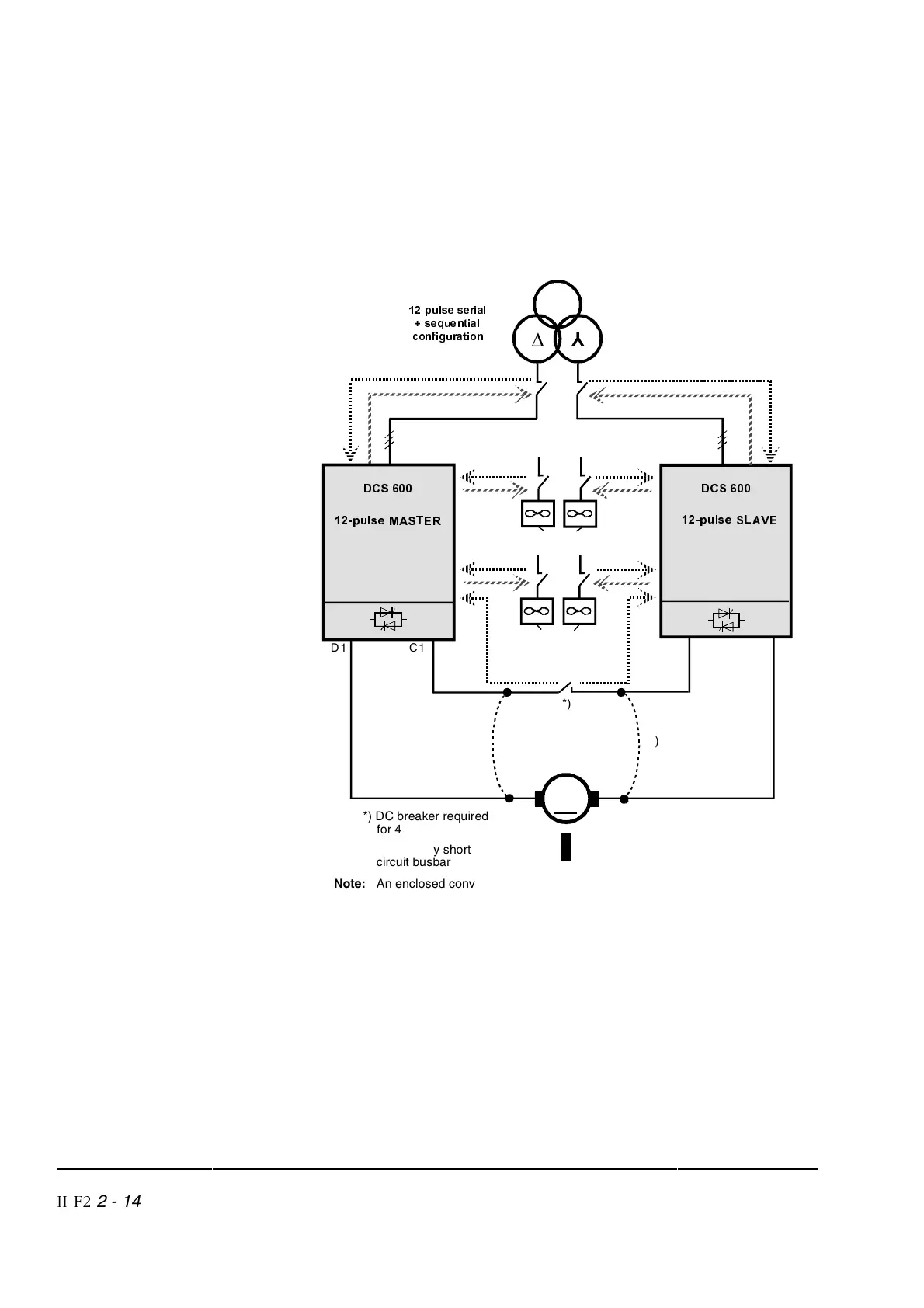
Figure 2/16 shows the recommended connection of the necessary
signals. Each converter is connected like a single 6 – pulse con-
verter.
In the slave converter the DI5 (emergency stop input) has to be
switched off by parameter
(12.16) = [0].
SXOVHVHULDO
VHTXHQWLDO
FRQILJXUDWLRQ
C1D1
**)
C1D1
*)
∆
<
*) DC breaker required
for 4-Q drives
SXOVH6/$9(
'&6
SXOVH0$67(5
'&6
Motor fans
Converter fans
Field
0
**)
**) Emergency short
circuit busbar
Note: An enclosed converter with special busbar design (option) can be ordered
from ABB Lampertheim for easy mounting of the emergency short circuit
busbar.
Figure 2/16