Chapter 3 – Twelve–Pulse Parallel Configurations with DCS 600
DCS 600 Manual for 12 – Pulse Operation
II F2
3 - 3
3.2 Twelve–pulse parallel Software configurations
12 – pulse communi-
cation via SDCS–
CON-2 channel V260
(12 – pulse link)
The DC thyristor power converters from the DCS 600 series are
equipped with a separate optical fibre DDCS link on the SDCS-
CON-2 board for the 12 – pulse communication (V260, located
close to connector X7). No other communication setup is required,
except a communication timeout parameter
COMM TIMEOUT 12P
(47.09).
This parameter defines the allowed number of control cy-
cles (3.3 ms at 50 Hz) without receiving a valid message. For the
12 – pulse slave, this parameter must be set from default value
“1”
to at least “4”.
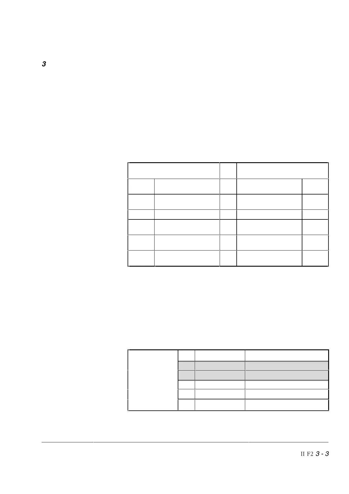
One DDCS dataset in each direction is exchanged between the two
converters. Their content is:
Dataset for 12 –
pulse parallel mode
12 – pulse Master 12 – pulse Slave
3.09 Control status of
12 – pulse master
⇒
Control status of
12 – pulse master
3.09
3.28
1
) Armature current ref-
erence
⇒
Armature current ref-
erence
3.28
1
)
--- ---
⇒
--- ---
3.10 Control status of
12 – pulse slave
⇐
Control status of
12 – pulse slave
3.10
2.21
2
) Act. armature current
of 12 – pulse slave
⇐
Act. converter current 1.15
--- Act. armature voltage
of slave
⇐
Act. armature voltage 1.13
1
) This AMC-table index exists in Software versions 15.605 or later
2
) 100 % = I
rated motor
rescaled from the master setting
12 – pulse Software
configuration for
parallel mode
The 12 – pulse Software configuration is based on a 12 – pulse
master converter and a 12 – pulse slave converter.
This is done by setting function specific (master/slave) parameters
and signals (the 12 – pulse related signals and parameters are
mentioned within this chapter; 12 – pulse parameters are mainly
inside parameter group 57).
The 12 – pulse mode is activated by setting the desired control
mode to parameter:
0: 6P SINGLE 6–pulse operation
1: 12P PAR MAS 12–pulse parallel master
Parallel 〉
mode 〉
2: 12P PAR SLA 12–pulse parallel slave
3: 12P SER MAS 12–pulse serial master
Serial/sequential 〉
mode 〉
4: 12P SER SLA 12–pulse serial slave
OPER MODE
SELECT
(15.16)
5: FIELD EXC Field exciter mode