Chapter 4 – Twelve–Pulse Serial / Sequential
Configurations with DCS 600
DCS 600 Manual for 12 – Pulse Operation
II F2
4 - 1
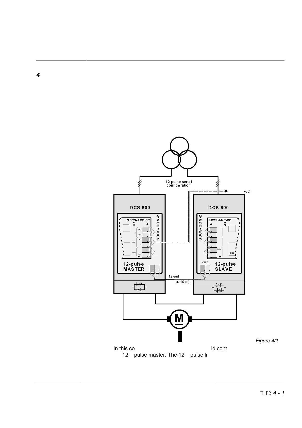
4.1 Twelve–pulse serial/sequential hardware configurations
The following figures show the most significant features of the 12 –
pulse
serial/sequential hardware configurations (max. output voltage
1600 V DC) with two DC thyristor power converters of the
DCS 600 se-
ries combined with the corresponding 12 – pulse control structures:
• Connection of converters in serial (sequential) configuration
• Master / Follower link [channel 2 on SDCS-AMC-DC boards]
• Master / Slave 12 – pulse communication link [channel V260 on
SDCS-CON-2 boards]
12 – pulse serial /
sequential configu-
ration with master /
slave 12 – pulse
communication link
C1D1 C1
D1
∆
<
6
'
&
6
&
2
1
D200
6'&6$0&' &
CH 3
TxD
RxD
CH 2
TxD
RxD
CH 0
TxD
RxD
D400
V260
TxDRxD
MASTER-
FOLLOWER
SDCS-AMC-DC
Channel (CH) 2
D200
6'&6$0&' &
CH 3
TxD
RxD
CH 2
TxD
RxD
CH 0
TxD
RxD
D400
6
'
&
6
&
2
1
V260
TxDRxD
SXOVH VHULDO
FRQILJX UDWLRQ
MASTER-
FOLLOWER
(further drives)
'&6
12-pulse Link
(max. 10 m)
'&6
SXOVH
0$67(5
SXOVH
6/$9(
0
Figure 4/1
In this combination speed, current and field control are performed by
the 12 – pulse master. The 12 – pulse link control directs the firing
angle of the slave.