Chapter 3 – Twelve–Pulse Parallel Configurations with DCS 600
II F2
3 - 6 DCS 600 Manual for 12 – Pulse Operation
Bridge reversal
In 6 – pulse op-
eration
With a 6 – pulse converter, the bridge reversal is initiated by
changing the polarity of the current reference. Upon zero current
detection, the bridge reversal is started after a delay. Depending on
the moment involved, the new bridge may be “fired” either in the
same or in the next cycle. In addition, switchover can be delayed by
a number of cycles programmed to parameter
REV DELAY (43.13).
This feature may prove useful when operating with large induc-
tances. Then the system changes to the selected bridge without
any further consideration.
Note: If the bridge reversal takes more than 2 control cycles longer
than the sum of the control cycles programmed to parameters
REV DELAY (43.13) and REV GAP (47.07), the fault 65 “REVER FLT”
(reversal fault) is activated.
In 12 – pulse op-
eration
The 12 – pulse bridge reversal function is the same as in 6 – pulse
operation. Depending on the firing angle, the current size, the cur-
rent alteration etc., the zero-current interval is extended by 1 to 2
cycles. In addition, the system delays the bridge reversal until both
current references polarities coincide, or until additional control cy-
cles programmed to parameter
REV DELAY (43.13) have elapsed.
If the bridge signals of master and slave are different for longer
than the control cycles (3.3 ms at 50 Hz) programmed to parameter
REV FAULT DELAY (47.08), the fault 65 “REVER FLT” (reversal fault)
is activated (by the master only). The parameter
REV FAULT DELAY
(47.08)
must be greater than the sum of parameters REV DELAY
(43.13)
and REV GAP (47.07). The two parameters (43.13) and (47.07)
must be set to same values in both converters.
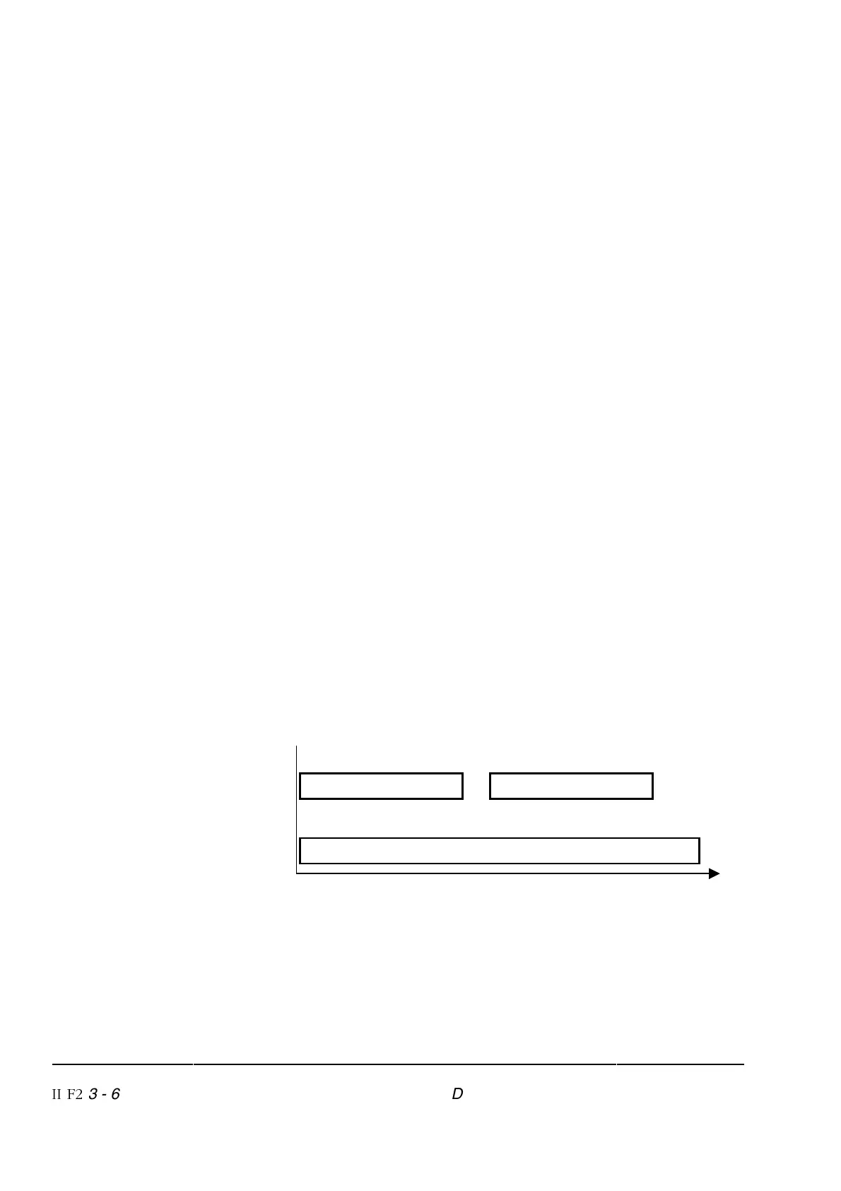
Delay function Zero current monitoring
REV DELAY (43.13) REV GAP (47.07)
Monitoring of master and slave bridge reversal
REV FAULT DELAY (47.08)
Reversal time
Figure 3/3: Time schedule for bridge reversal in 12 – pulse operation