Chapter 2 – Twelve–Pulse Technology
DCS 600 Manual for 12 – Pulse Operation
II F2
2 - 13
Hardware connec-
tions
There are a lot of possibilities to connect the control and acknowl-
edge signal of each converter. But It is important to select a con-
nection which is also suitable for emergency operation.
The Slave still needs the acknowledge signal from the auxiliary cir-
cuit.
For emergency operation it is required to have the FEX – Link con-
nection to the slave (depends on individual case).
In 12 – pulse operation this slave connection is out of operation
⇒ Parameter
(15.05) = [0].
The emergency parameter set must include Parameter
(15.05) and
switch off the FEX – Link communication of the converter which is
not in use.
In the slave converter the DI5 (emergency stop input) has to be
switched off by parameter
(12.16) = [0].
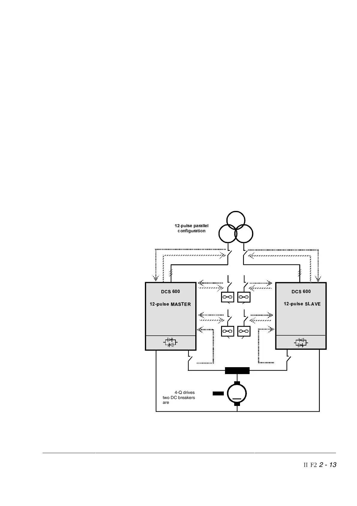
12 – pulse par-
allel configuration
Figure 2/15 shows the recommended connection of the necessary
signals. Each converter is connected in a similar way to a single
6 – pulse converter.
T-REACTOR
Field
0
C1
D1
*)
C1D1
*)
∆
<
SXOVHSDUDOOHO
FRQILJXUDWLRQ
*) For 4-Q drives
two DC breakers
are recommended
SXOVH6/$9(
'&6
SXOVH0$67(5
'&6
Motor fans
Converter fans
Figure 2/15