Chapter 4 – Twelve–Pulse Serial / Sequential Configurations with DCS 600
DCS 600 Manual for 12 – Pulse Operation
II F2
4 - 7
Measuring the DC
voltage (serial /
sequential mode)
Changes of the voltage measurement channel required for 12 –
pulse serial and sequential configurations:
The master converter has to measure the double DC voltage of the
original 6 – pulse DC voltage; for that reason the design of the high-
resistance voltage measurement circuit integrated in the units of the
series DCS 600 requires hardware changes of the internal voltage
measurement channel if the units are used in 12 – pulse serial and
sequential configurations.
Note: These hardware changes in connection with a 12 –
pulse serial and sequential configuration can only be
applied to the units DCS 600 of the sizes
C3 (900 A…2000A) with max. supply voltage 350 VAC
C4 (2050 A…5150A) with max. supply voltage 600 VAC
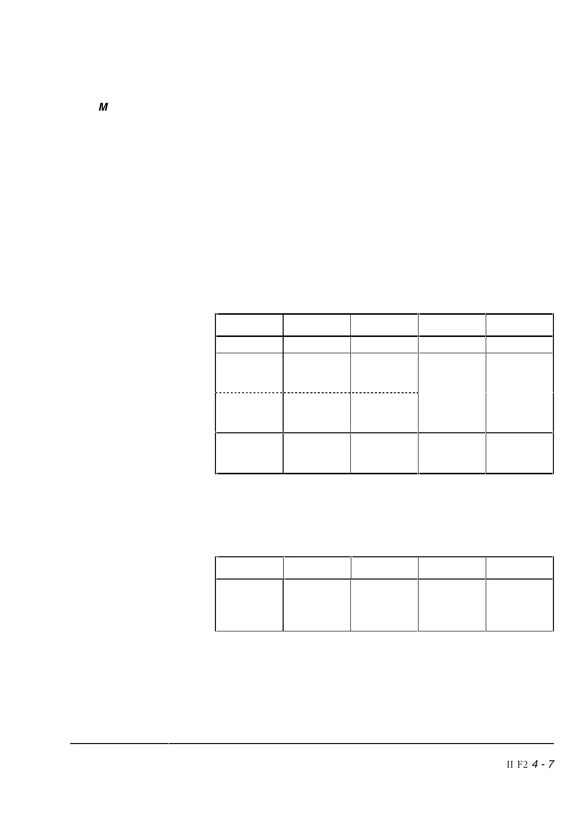
Table: Changes of the voltage measurement channel required
for 12 – pulse serial and sequential configurations
Sizes DC [Amps] Supply [V] Solution 1 Solution 2
C1 + C2 25…700 200…600 Not possible Not possible
C3 900…2000 200…350 *) SDCS-
PIN-51
+
AC + DC
voltage
transducers
C4 2050…5150 200…500 HW-coding
and
-SW-coding
C4 2050… 5150 500 … 600 – AC + DC
voltage
transducers
*) See SDCS-PIN-51 modification (Solution 1)
An extended voltage range can be applied to a special power circuit
configuration (sandwich configuration) for C4 (2050A…5150A) with
max. supply voltage 1000 VAC.
Sizes DC [Amps] Supply [V] Solution 1 Solution 2
C4
Sandwich
configuration
2050… 5150 200 … 1000 SDCS
PIN51
+ HW and
SW coding
AC + DC
voltage
transducers
see page 4-14