Chapter 4 – Twelve–Pulse Serial / Sequential Configurations with DCS 600
DCS 600 Manual for 12 – Pulse Operation
II F2
4 - 11
Solution 2
:
AC + DC voltage
transducers
[continued]
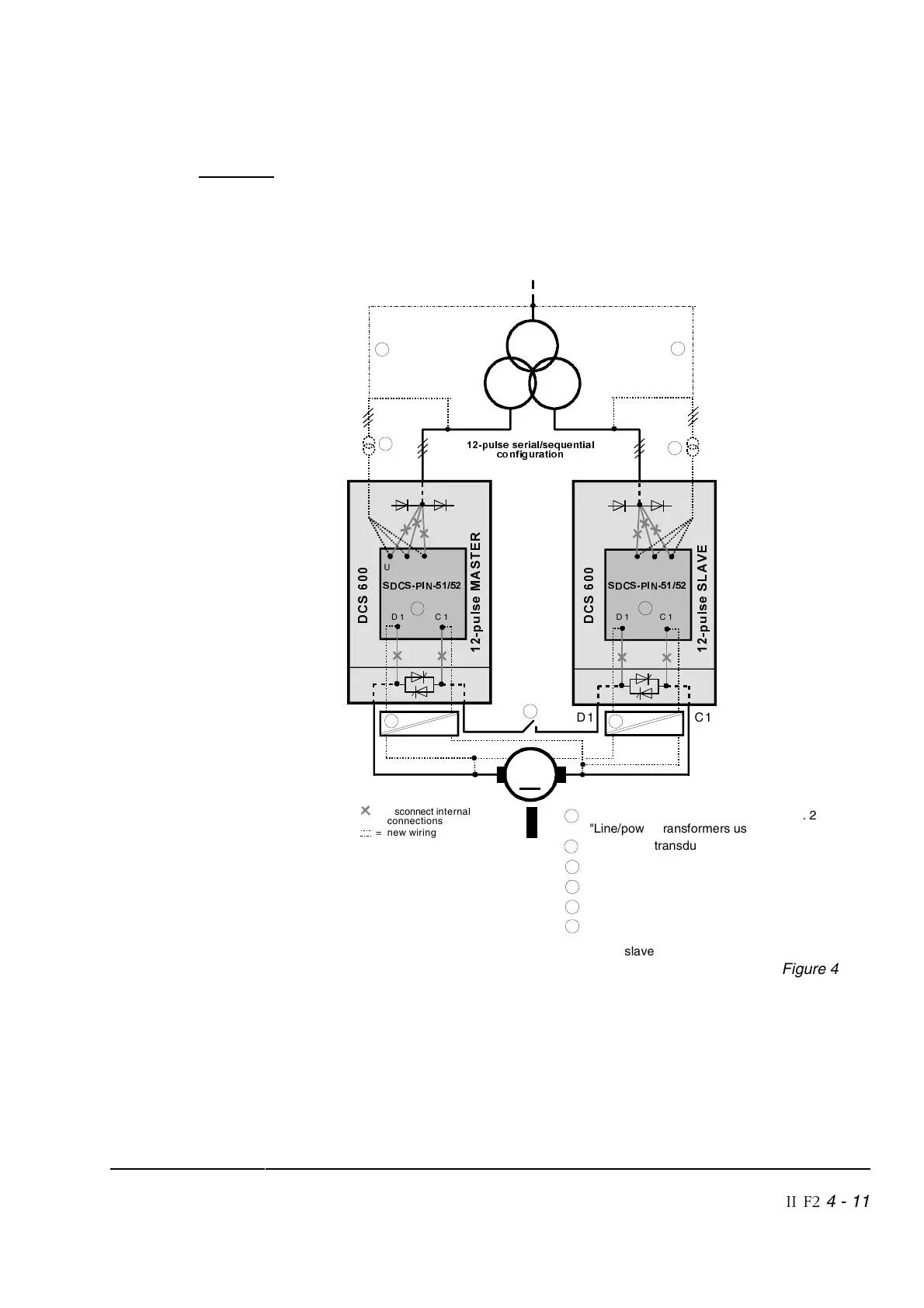
Normal connection with one common DC motor:
This high voltage measurement circuit is performed by galvanic
isolation devices (see
Figure 4/4).
The correct EMF feedback is selected by the parameter
ADJ UDC
(47.10) = [0,5].
C1
D1
∆
<
SXOVHVHULDOVHTXHQWLDO
FRQILJXUDWLRQ
'
&
6
S
X
O
V
H
0
$
6
7
(
5
=
disconnect
internal
connections
= new wiring
D 1 C 1
6'&63,1
C1
D1
S
X
O
V
H
6
/
$
9
(
D 1 C 1
U 1 V 1 W 1
U 1 V 1
W 1
'
&
6
4
2
1
5
1 Recommended connection (see chapt. 2
"Line/power transformers used in ...")
2 AC voltage transducer (see separate manual)
3 DC voltage transducer (see separate manual)
4 High-speed DC breaker (required for 4-Q drives)
5 Modification
(see separate manual)
2
1
5
6'&63,1
3
0
6
6 This DC voltage measurement channel is only
used for single six pulse emergency operation
of the slave
Figure 4/4
Note: The input for the armature overvoltage protection
(28.22) and
rated motor voltage
(99.02) are at 50 % of the actual armature
voltage value!
Example: Supply voltage = 600 V
(99.02) = [650 V]
Rated motor voltage = 1300 V
(28.22) = [125 %]
⇒ 1500 V