Chapter 4 – Twelve–Pulse Serial / Sequential Configurations with DCS 600
DCS 600 Manual for 12 – Pulse Operation
II F2
4 - 13
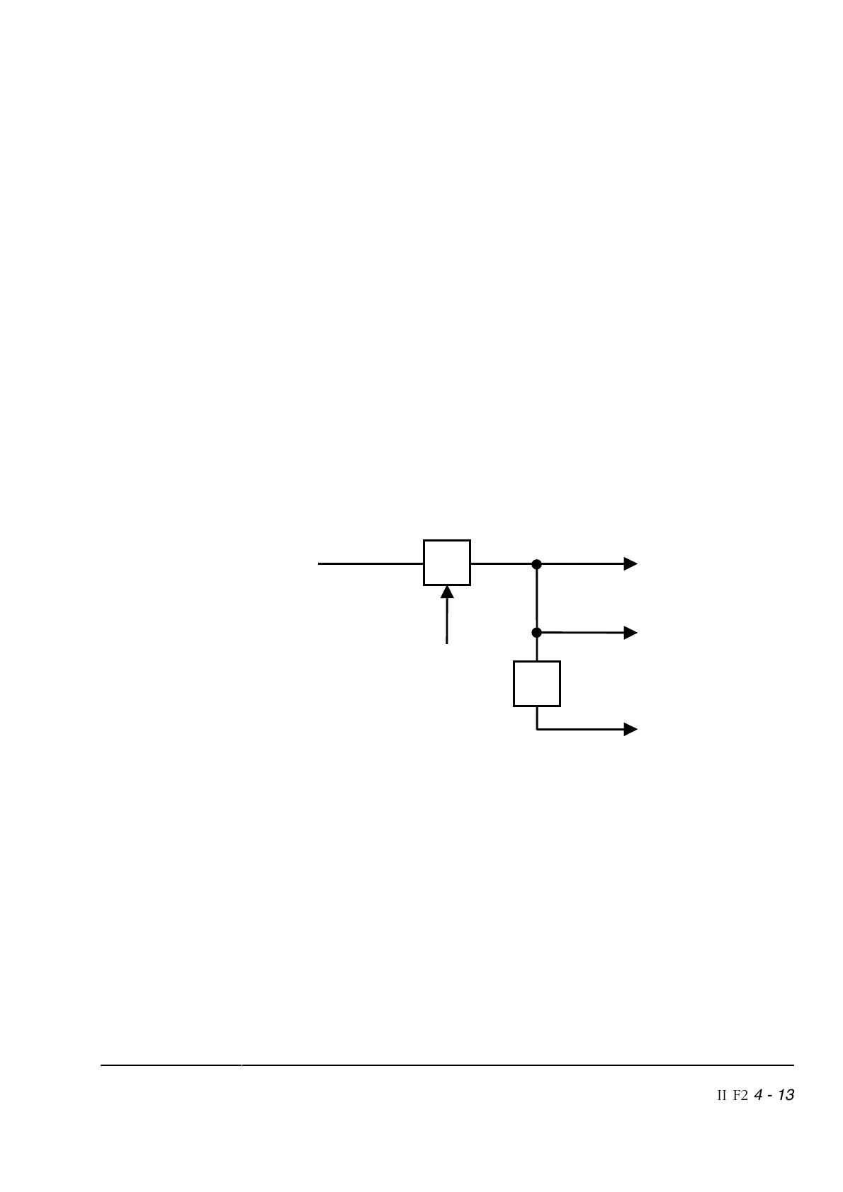
Measuring the DC
voltage (serial /
sequential mode)
[continued]
In the serial and sequential mode the software signals relevant to
the voltage are rescaled according to the doubled output voltage of
the configuration. This rescaling is valid for the master and the
slave as well. The monitoring of the signals is different depending
on whether CDP 312 / DriveWindow or APC / AC 80 is used.
The motor terminal voltage is shown by the following signals:
RL ARM VOLT ACT (1.13) ⇒ 135 % U
S
[4096] equals
2.7 x U
supply
(42.06)
ARM VOLT ACT (1.14)
⇒ 2 V equals 2 V
(CDP 312 / DriveWindow)
[1] equals 2 V
(APC / AC 80)
RL EMF VOLT ACT (1.17) ⇒ 135 % U
S
[3786] equals
2.7 x U
supply
(42.06)
EMF VOLT ACT (1.18)
⇒ 2 V equals 2 V
(CDP 312 / DriveWindow)
[1] equals 2 V
(APC / AC 80)
Figure 4/6
1
= 2
DriveWindow
CDP 312
Hardware
DC voltage
measurement
ADJ UDC
x2
EMF control
EMF feedbac
x
APC
Fieldbus
Advant
Display of
real values
(1.14)
(1.18)
(1.14)
(1.18)