EL3000 CONTINUOUS GAS ANALYZERS | OI/EL3000-EN REV. D 191
Cleaning the Fidas24 air jet injector
When does a housing purge become necessary?
It is necessary to clean the air jet injector when the sample gas
outlet pressure is too high, i.e. when the negative pressure can
no longer be adjusted to p
abs
< 600 hPa.
Requisite Material
• Open-ended spanner 12 mm and 14 mm
• O-ring set for the detector (order number 769343)
• Ultrasonic bath with aqueous cleaner
(e.g. Extran® MA 01 alkaline)
• High-temperature grease (order number 772341)
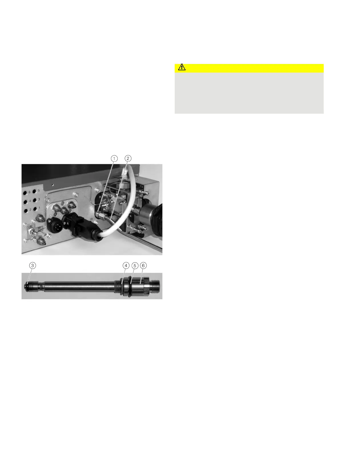
Clean air jet injector
Exhaust air outlet with the air jet injector screwed in
Exhaust pipe
O-ring
O-ring
O-ring
The removed air jet injector
Figure 106: Removing the air jet injector
Risk of burns
Risk of burns at the heated sample gas connection
(temperature approx. 180 °C)!
• Before working on the heated sample gas connection,
switch off the power supply and allow the sample gas
connection to cool for about 30 minutes.
1. Disconnect the supply of sample gas to the analyzer module!
Power-down the 115 / 230 V AC power supply to the gas
analyzer and heater, as well as the separate 24 V DC supply to
the analyzer module, if applicable!
2. Unscrew the exhaust air pipe
2 from the exhaust air
outlet
1
(open-end wrench 12 mm).
3. Unscrew the air jet injector from the exhaust air outlet
1
(open-end wrench 14 mm).
4. Clean the air jet injector in an ultrasonic bath. Use an
aqueous cleaner (e.g. Extran®).
5. Replace O-rings
3/4/5 with new O-rings.
Note
• When cleaning the air jet injector, always replace all three
O-rings! Dirty or damaged O-rings impair the suction
power of the air jet injector; this can lead to the failure of
the Fidas24.
• Lightly grease all three O-rings with high temperature
grease (part number 772341) before inserting them.
6. Screw the air jet injector
6 into the exhaust air outlet .
Ensure that the O-rings are seated correctly.
7. Screw the exhaust air pipe
2 onto the exhaust air outlet 1.
8. Restore the sample gas supply to the analyzer module.
9. Switch on the power supply.
10. Check the manipulated variables of the internal pressure
regulators for the operational gases, and adjust as
necessary, refer to Fidas24 – Commissioning the gas
analyzer on page 104.
11. Once the warm-up phase is complete, calibrate the gas
analyzer.