Table 634: The automatic selection of operation modes for regulators in the Master/Follower
example
CB1 CB2 CB3 Regulator 1 Regulator 2
Open Open Open Manual Manual
Open Open Closed Manual Auto single
Open Closed Open Manual Manual
Open Closed Closed Manual Auto single
Closed Open Open Auto single Manual
Closed Open Closed Auto single Auto single
Closed Closed Open Auto single Manual
Closed Closed Closed Auto parallel
(Master)
Auto parallel
mode
= "Auto
master''
Auto parallel
(Follower)
Auto parallel
mode
= "Auto
follower"
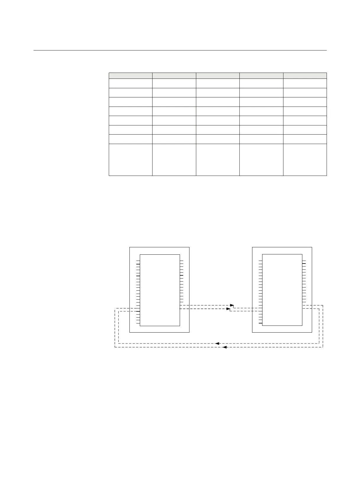
Configuration example for the Auto parallel (MCC) mode
The purpose of the Auto parallel (MCC) mode is to minimize the circulating
current between the parallel transformers. The data exchange between the
regulators can be done with the horizontal GOOSE communication.
OLATCC
I_A
I_B
I_C
U_AB
TR1_TAP_POS
TR2_TAP_POS
TR3_TAP_POS
RAISE_LOCAL
LOWER_LOCAL
TAPCHG_FLLW
PARALLEL
AUTO
CON_STATUS
LTC_BLOCK
TCO
RSV
TR1_I_AMPL
TR1_I_ANGL
TR2_I_AMPL
TR2_I_ANGL
TR3_I_AMPL
TR3_I_ANGL
RAISE_OWN
LOWER_OWN
FLLW1_CTL
FLLW2_CTL
FLLW3_CTL
BLKD_I_LOD
BLKD_U_UN
BLKD_U_OV
BLKD_I_CIR
BLKD_LTCBLK
ALARM
PAR_FAIL
PARALLEL
AUTO
TIMER_ON
TR0_I_AMPL*
TR0_I_ANGL*
IED 1 / Regulator 1 IED 2 / Regulator 2
GOOSE communication
GOOSE communication
* Only for GOOSE Engineering * Only for GOOSE Engineering
GUID-1D6F1FD5-58AD-4AB1-B3F4-3414392CFEE1 V2 EN
Figure 406: Two parallel transformers and the horizontal connection via
GOOSE to transfer current and the phase angle information when
the MCC principle is used
Configuration example for the Auto parallel (NRP) mode
The advantage of the Negative Reactance Principle (NRP) operation mode is that
no wiring or communication is needed between the IEDs. The voltage regulators
operate independently. However, for the cases where there is an occasional
1YHT530004D05 D Section 9
Control functions
615 series 755
Technical Manual