compensated networks or of the earthing resistor in earthed networks. As a result the
characteristic angle is set automatically to suit the earthing method used. The
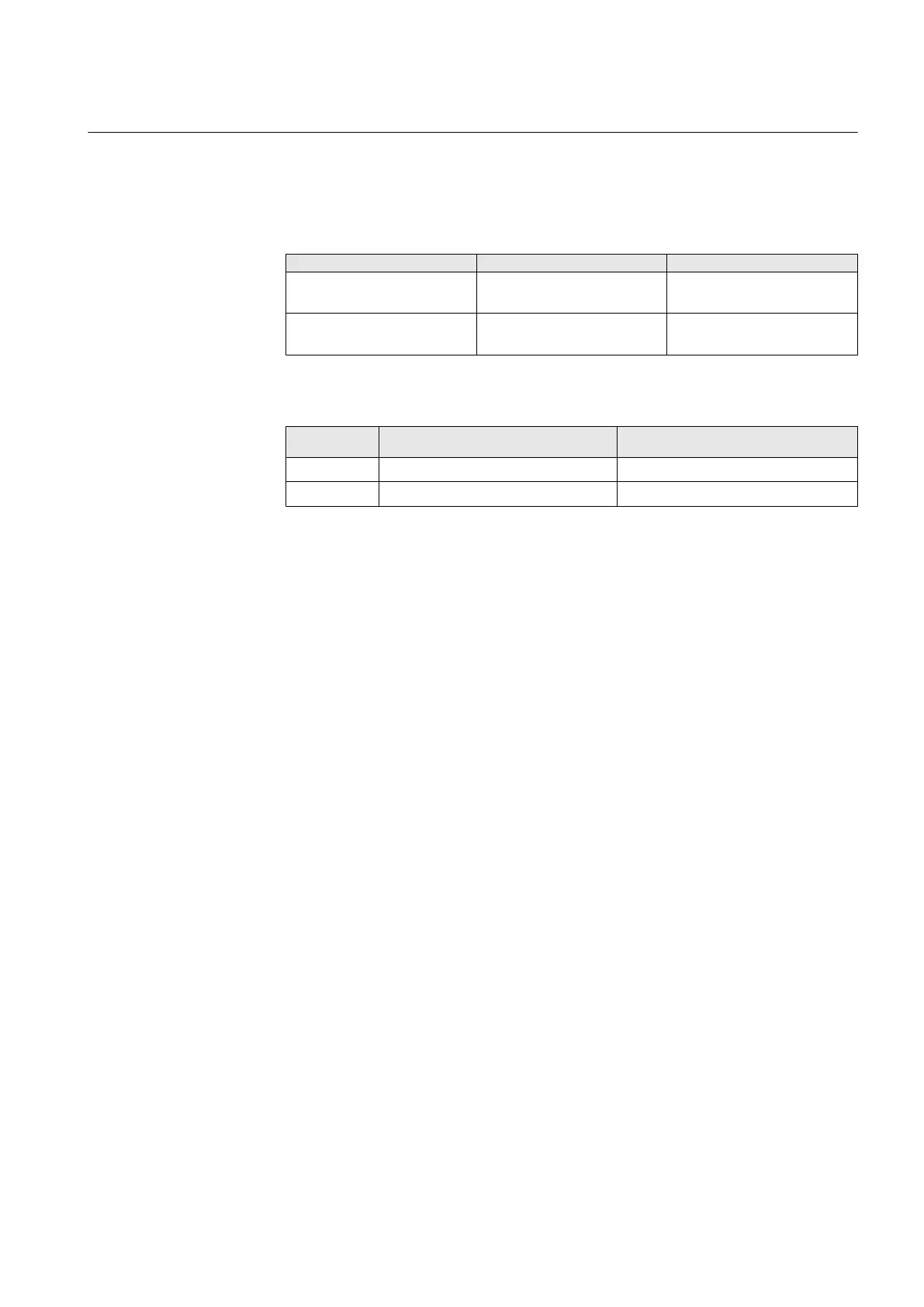
RCA_CTL input can be used to change the I
0
characteristic:
Table 63: Relay characteristic angle control in I
0
sin(φ) and I
0
cos(φ) operation criteria
Operation criteria setting: RCA_CTL = FALSE RCA_CTL = TRUE
I
0
sin(φ) Actual operation criteria: I
0
sin(φ) Actual operation criteria:
I
0
cos(φ)
I
0
cos(φ) Actual operation
criteria:I
0
cos(φ)
Actual operation criteria: I
0
sin(φ)
Table 64: Characteristic angle control in phase angle operation mode
Characteristic
angle
setting
RCA_CTL = FALSE RCA_CTL = TRUE
-90° φRCA = -90° φRCA = 0°
0° φRCA = 0° φRCA = -90°
Usage of the extended phase angle characteristic
In addition to the RCA_CTL input, the extended phase angle characteristic can be
used to disconnect the compensation coil in compensated networks. When the
extended operation area is used, the operation area is wide enough to detect earth
faults selectively in compensated networks regardless of whether the compensation
coil is connected or not. Therefore, the RCA_CTL input is not required if the extended
operation area is used.
Sometimes the distance between the start point and the IED is long which makes it
impractical to apply the scheme based on signal wiring between the relay and the
Petersen coil or the earthing resistor. This is the case for instance, when a directional
earth-fault relay is used in an MV-switching substation some kilometers from the
HV/MV -substation in which the earthing facilities are located. Another example is
when HV/MV-substations are connected in parallel but located far from each other.
It is easy to give the tripping sector such a width that all possible directions of the
I
0
-phasors of a faulty line are covered by one and the same sector. Thus, the problem
of setting the characteristic angle according to the earthing status of the network is
easily solved. There is no need to change any settings when a Petersen coil or an
earthing resistor is switched on or off. Auxiliary switches and other pieces of extra
hardware are no longer required for ensuring the selectivity of the directional earth-
fault protection.
1MRS756378 D Section 5
Protection functions
REF615 151
Application Manual