command to the circuit breaker, either local or remote, also blocks the autoreclose
function via the CBXCBR-selected signal.
The circuit breaker availability for the autoreclosure sequence is expressed with the
CB_RDY input in DARREC1. In the configuration, this signal is not connected to
any of the binary inputs. As a result, the function assumes that the breaker is available
all the time.
The autoreclose sequence in progress indication is connected to the alarm LED 11.
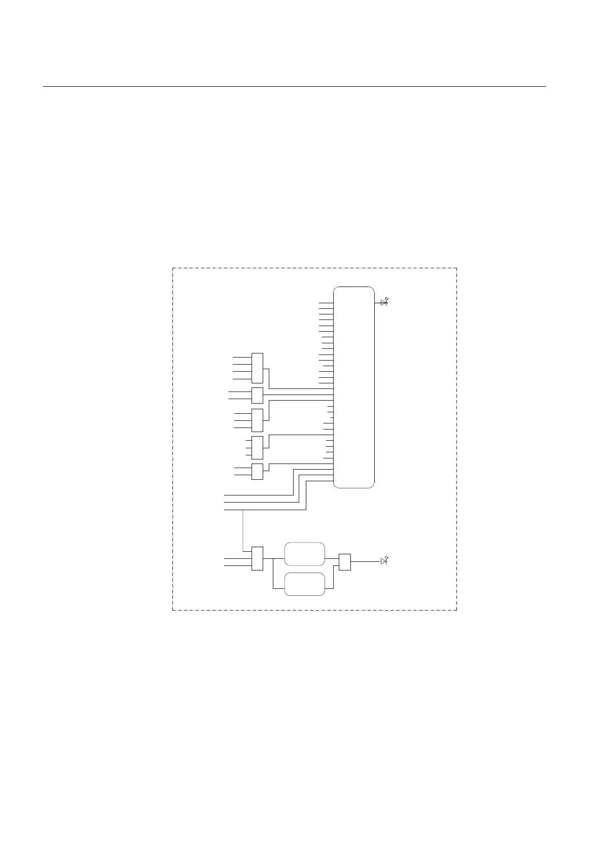
3.3.3.2 Functional diagrams for disturbance recorder and trip circuit
supervision
PHLPTOC1-start
PHHPTOC1-start
PHHPTOC2-start
PHIPTOC1-start
NSPTOC1-start
NSPTOC2-start
DEFLPDEF1-start
DEFLPDEF2-start
DEFHPDEF1-start
INTRPTEF1-start
EFHPTOC1-start
PDNSPTOC1-start
T1PTTR1-start
CCRBRF1-trret
CCRBRF1-trbu
OR
PHLPTOC1-operate
PHHPTOC1-operate
PHHPTOC2-operate
PHIPTOC1-operate
LED7 (DR TRIGGERED)
OR
OR
INTRPTEF1-operate
EFHPTOC1-operate
PDNSPTOC1-operate
INRPHAR1-blk2h
T1PTTR1-operate
OR
ARCSARC1-operate
ARCSARC2-operate
ARCSARC3-operate
DARREC1-inpro
OR
NSPTOC1-operate
NSPTOC2-operate
ARCSARC1-fault_arc_det
ARCSARC2-fault_arc_det
ARCSARC3-fault_arc_det
DEFLPDEF1-operate
DEFLPDEF2-operate
DEFHPDEF1-operate
DARREC1-close cb
DARREC1-unsuc_recl
BI 1 (Blocking)
BI 2 (CB Closed)
BI 3 (CB Open)
DISTURBANCE RECORDER
TCSSCBR1
ALARM
BLOCK
TCSSCBR2
ALARM
BLOCK
OR
OR
TRPPTRC1- trip
TRPPTRC2- trip
LED9 (TCS ALARM)
TRIP CIRCUIT SUPERVISION
RDRE1
TRIGGEREDBI#1
BI#2
BI#3
BI#4
BI#5
BI#6
BI#7
BI#8
BI#9
BI#10
BI#11
BI#12
BI#13
BI#14
BI#15
BI#16
BI#17
BI#18
BI#19
BI#20
BI#21
BI#22
BI#23
BI#24
BI#25
BI#26
BI#27
BI#28
BI#29
BI#30
BI#31
BI#32
A071324 V4 EN
Figure 13: Disturbance recorder
The disturbance recorder has 64 digital inputs, of which 32 are connected as default.
All start and operate signals from the protection stages are routed to trigger the
disturbance recorder or alternatively only to be recorded by the disturbance recorder
depending on the parameter settings. Additionally, the selected autorecloser, the ARC
protection signals and the three binary inputs from X120 are also connected.
Section 3 1MRS756378 D
REF615 variants
42 REF615
Application Manual