3.4.3.2 Functional diagram for disturbance recorder and trip circuit supervision
PHLPTOC1-start
PHHPTOC1-start
PHHPTOC2-start
PHIPTOC1-start
NSPTOC1-start
NSPTOC2-start
DEFLPDEF1-start
DEFLPDEF2-start
DEFHPDEF1-start
INTRPTEF1-start
EFHPTOC1-start
PDNSPTOC1-start
T1PTTR1-start
CCRBRF1-trret
CCRBRF1-trbu
OR
PHLPTOC1-operate
PHHPTOC1-operate
PHHPTOC2-operate
PHIPTOC1-operate
LED7 (DR TRIGGERED)
OR
OR
INTRPTEF1-operate
EFHPTOC1-operate
PDNSPTOC1-operate
INRPHAR1-blk2h
T1PTTR1-operate
OR
ARCSARC1-operate
ARCSARC2-operate
ARCSARC3-operate
DARREC1-inpro
OR
NSPTOC1-operate
NSPTOC2-operate
ARCSARC1-fault_arc_det
ARCSARC2-fault_arc_det
ARCSARC3-fault_arc_det
DEFLPDEF1-operate
DEFLPDEF2-operate
DEFHPDEF1-operate
DARREC1-close cb
DARREC1-unsuc_recl
BI 1 (Blocking)
BI 2 (CB Closed)
BI 3 (CB Open)
DISTURBANCE RECORDER
TCSSCBR1
ALARM
BLOCK
TCSSCBR2
ALARM
BLOCK
OR
OR
TRPPTRC1- trip
TRPPTRC2- trip
LED9 (TCS ALARM)
TRIP CIRCUIT SUPERVISION
RDRE1
TRIGGEREDBI#1
BI#2
BI#3
BI#4
BI#5
BI#6
BI#7
BI#8
BI#9
BI#10
BI#11
BI#12
BI#13
BI#14
BI#15
BI#16
BI#17
BI#18
BI#19
BI#20
BI#21
BI#22
BI#23
BI#24
BI#25
BI#26
BI#27
BI#28
BI#29
BI#30
BI#31
BI#32
A071324 V4 EN
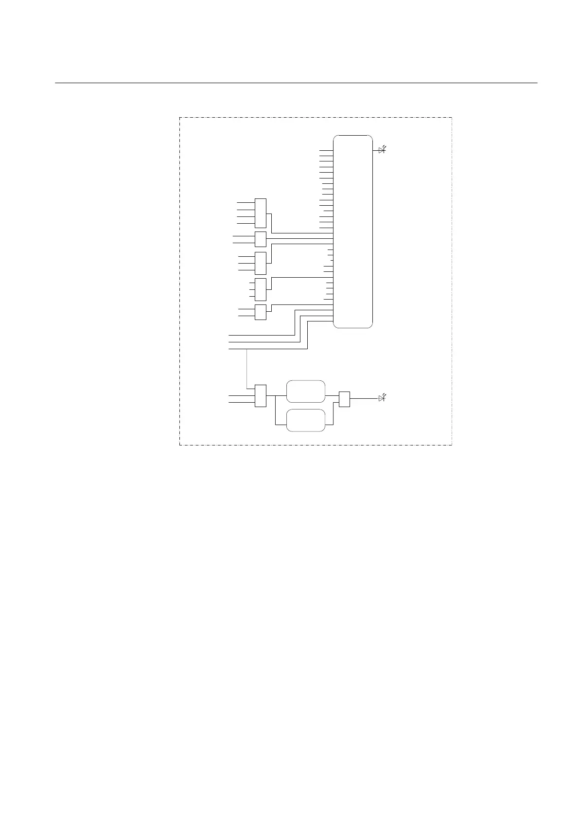
Figure 21: Disturbance recorder
The disturbance recorder has 64 digital inputs, of which 32 are connected as default.
All start and operate signals from the protection stages are routed to trigger the
disturbance recorder or alternatively only to be recorded by the disturbance recorder
depending on the parameter settings. Additionally, the selected autorecloser, the ARC
protection signals and the three binary inputs from X120 are also connected.
Two separate TCS functions have been included: TCSSCBR1 for PO3 (X100:16-19)
and TCSSCBR2 for PO4 (X100:20-23). Both functions are blocked by the Master
Trip (TRPPTRC1 and TRPPTRC2) and the circuit breaker open position signal. The
TCS alarm indication is connected to LED 9.
1MRS756378 D Section 3
REF615 variants
REF615 53
Application Manual