Section 4 Basic functions
4.1 General parameters
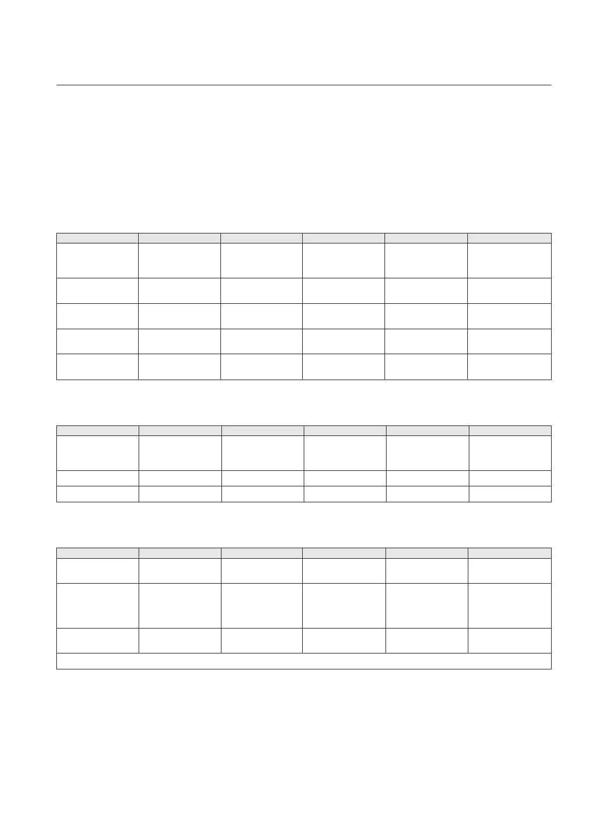
Table 23: Analog channel settings, phase currents
Parameter Values (Range) Unit Step Default Description
Secondary current 1=0.2A
2=1A
3=5A
2=1A Rated secondary
current
Primary current 1.0...6000.0 A 0.1 100.0 Rated primary
current
Amplitude corr. A 0.900...1.100 0.001 1.000 Phase A amplitude
correction factor
Amplitude corr. B 0.900...1.100 0.001 1.000 Phase B amplitude
correction factor
Amplitude corr. C 0.900...1.100 0.001 1.000 Phase C amplitude
correction factor
Table 24: Analog channel settings, residual current
Parameter
Values (Range) Unit Step Default Description
Secondary current 1=0.2A
2=1A
3=5A
2=1A Secondary current
Primary current 1.0...6000.0 A 0.1 100.0 Primary current
Amplitude corr. 0.900...1.100 0.001 1.000 Amplitude correction
Table 25: Analog channel settings, phase voltages
Parameter
Values (Range) Unit Step Default Description
Primary voltage 0.001...440.000 kV 0.001 20.000 Primary rated
voltage
Secondary voltage 1=100V
2=110V
3=115V
4=120V
1=100V Secondary rated
voltage
VT connection 1=Wye
2=Delta
2=Delta Wye or delta VT
connection
Table continues on next page
1MRS756378 D Section 4
Basic functions
REF615 111
Application Manual