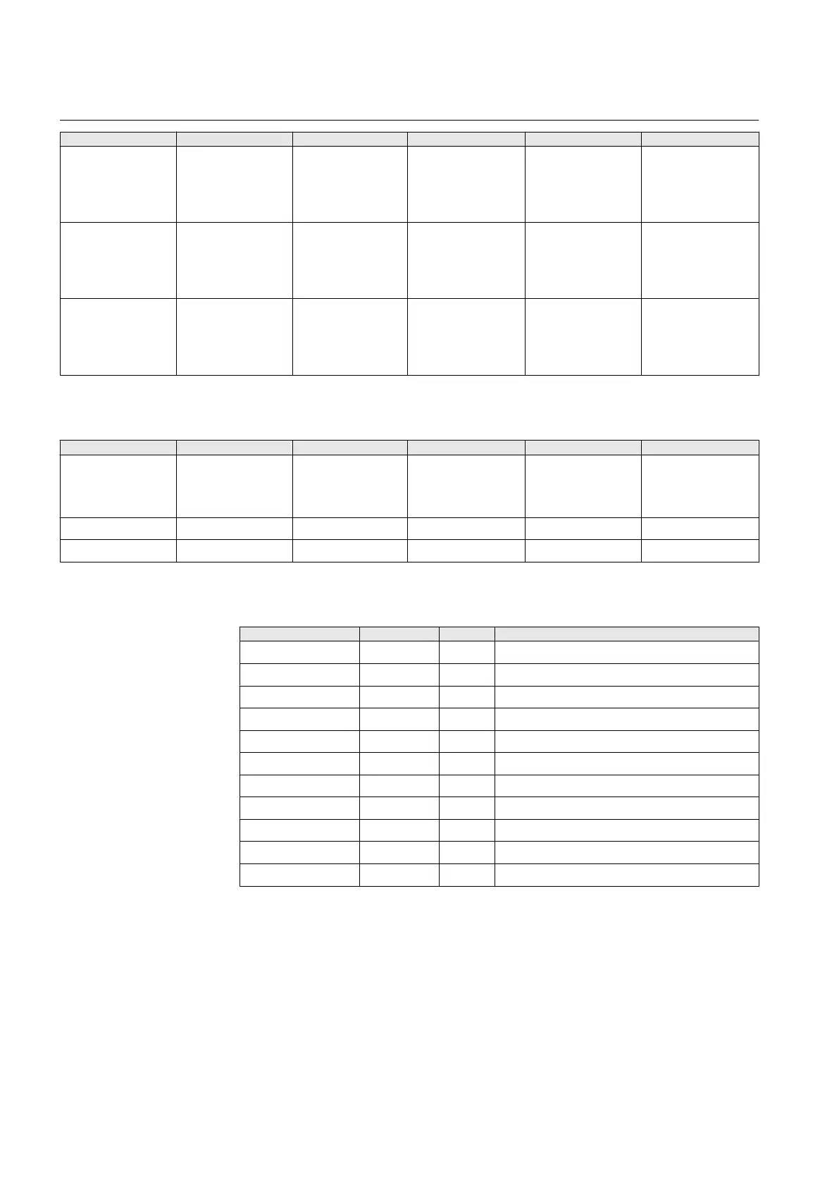
Parameter Values (Range) Unit Step Default Description
Amplitude corr. A 0.900...1.100 0.001 1.000 Phase A Voltage
phasor magnitude
correction of an
external voltage
transformer
Amplitude corr. B 0.900...1.100 0.001 1.000 Phase B Voltage
phasor magnitude
correction of an
external voltage
transformer
Amplitude corr. C 0.900...1.100 0.001 1.000 Phase C Voltage
phasor magnitude
correction of an
external voltage
transformer
Table 26: Analog channel settings, residual voltage
Parameter Values (Range) Unit Step Default Description
Secondary voltage 1=100V
2=110V
3=115V
4=120V
1=100V Secondary voltage
Primary voltage 0.001...440.000 kV 0.001 11.547 Primary voltage
Amplitude corr. 0.900...1.100 0.001 1.000 Amplitude correction
Table 27: Alarm LED input signals
Name
Type Default Description
Alarm LED 1 BOOLEAN 0=False Status of Alarm LED 1
Alarm LED 2 BOOLEAN 0=False Status of Alarm LED 2
Alarm LED 3 BOOLEAN 0=False Status of Alarm LED 3
Alarm LED 4 BOOLEAN 0=False Status of Alarm LED 4
Alarm LED 5 BOOLEAN 0=False Status of Alarm LED 5
Alarm LED 6 BOOLEAN 0=False Status of Alarm LED 6
Alarm LED 7 BOOLEAN 0=False Status of Alarm LED 7
Alarm LED 8 BOOLEAN 0=False Status of Alarm LED 8
Alarm LED 9 BOOLEAN 0=False Status of Alarm LED 9
Alarm LED 10 BOOLEAN 0=False Status of Alarm LED 10
Alarm LED 11 BOOLEAN 0=False Status of Alarm LED 11
Section 4 1MRS756378 D
Basic functions
112 REF615
Application Manual