protection signals and the three binary inputs from X120 are also connected, as well
as the autorecloser external start command from the binary input 2 (X110:3-4).
Two separate TCS functions are included: TCSSCBR1 for PO3 (X100:16-19) and
TCSSCBR2 for PO4 (X100:20-23). Both functions are blocked by the Master Trip
(TRPPTRC1 and TRPPTRC2) and the circuit breaker open position signal. The TCS
alarm indication is connected to LED 9.
3.6.3.3 Functional diagrams for control and interlocking
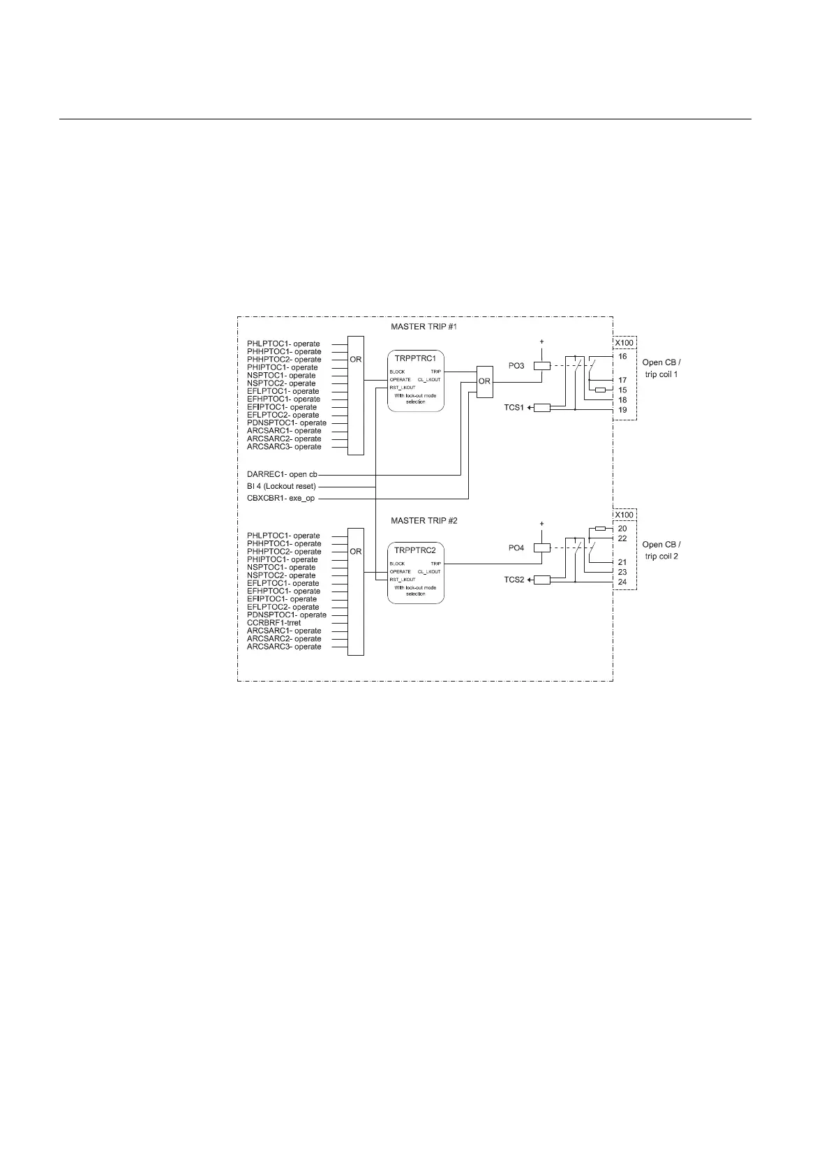
A071358 V4 EN
Figure 38: Master trip
The operate signals from the protections described above are connected to the two
trip output contacts PO3 (X100:16-19) and PO4 (X100:20-23) via the corresponding
Master Trips TRPPTRC1 and TRPPTRC2. The open control commands to the circuit
breaker from local or remote CBXCBR1-exe_op or from the auto-recloser
DARREC1-open_cb are connected directly to the output PO3 (X100:16-19).
The TRPPTRC1 and 2 blocks provide the lockout/latching function, event generation
and the trip signal duration setting. If the lockout operation mode is selected, the
binary input 4 (X120:5-6) is assigned to the RST_LKOUT input of the Master Trip
to enable external reset with a push button.
Section 3 1MRS756378 D
REF615 variants
76 REF615
Application Manual