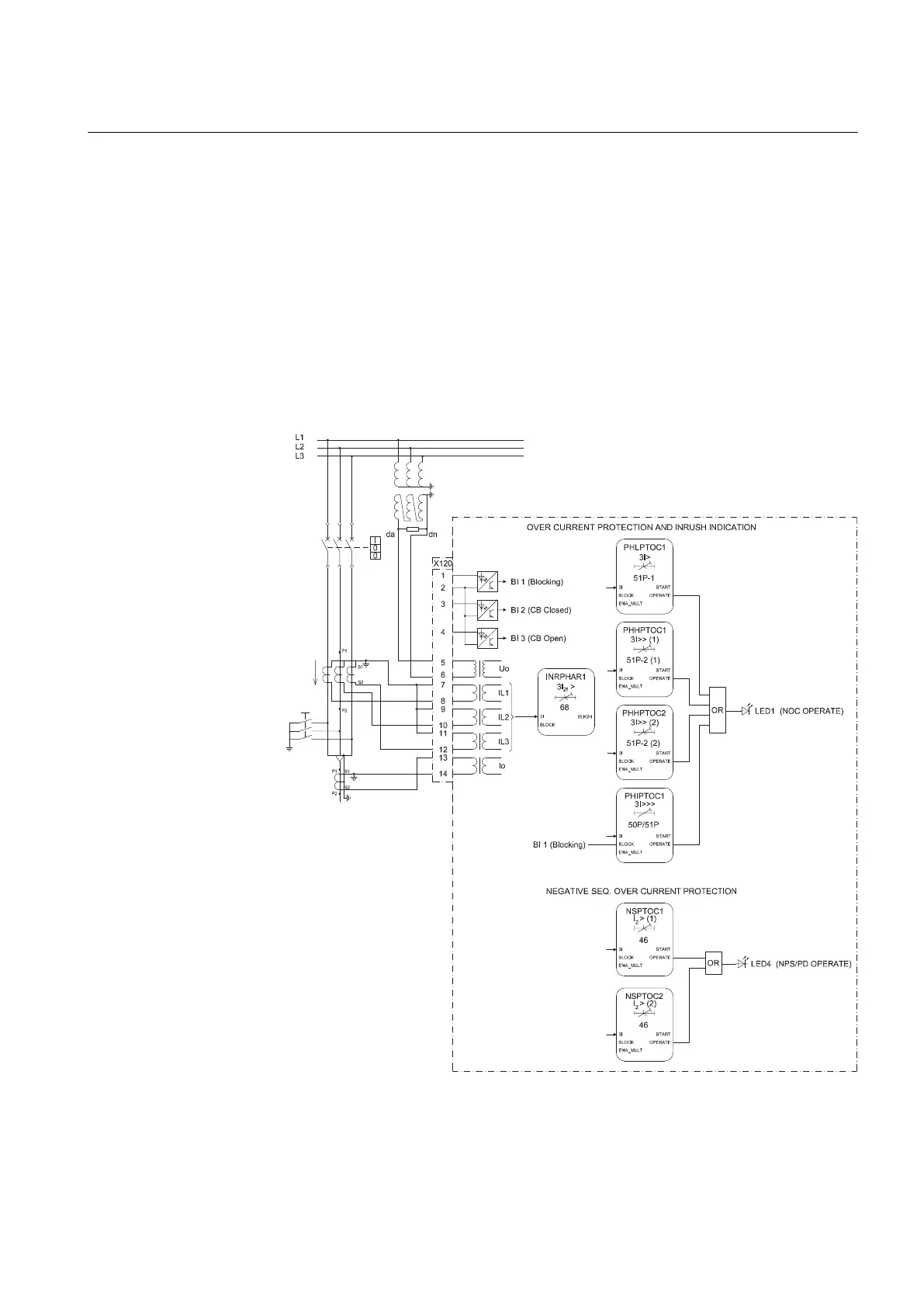
The analog channels are assigned to different functions as shown in the functional
diagrams. The common signal marked with 3I represents the three phase currents.
The signal marked with I
0
represents the measured residual current via a core balance
CT. The signal marked with U
0
represents the measured residual voltage via open
delta connected VTs.
The EFHPTOC protection function block for double (cross-country) earth-faults uses
the calculated residual current originating from the measured phase currents.
3.3.3.1 Functional diagrams for protection
The following functional diagrams describe the IED’s protection functionality in
detail and according to the factory set default connections in SMT.
A071316 V3 EN
Figure 9: Overcurrent protection
1MRS756378 D Section 3
REF615 variants
REF615 37
Application Manual