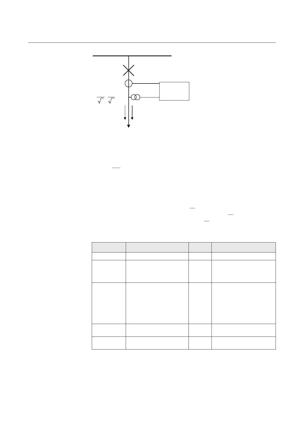
110kV Busbar
110kV OHL
P Q
600/1 A
IEC09000039-1-EN V2 EN
Figure 105: Single line diagram for 110kV OHL application
In order to monitor, supervise and calibrate the active and reactive power as indicated
in figure 105 it is necessary to do the following:
1. Set correctly CT and VT data and phase angle reference channel PhaseAngleRef
using PCM600 for analog input channels
2. Connect, in PCM600, measurement function to three-phase CT and VT inputs
3. Set under General settings parameters for the Measurement function:
• general settings as shown in table 26.
• level supervision of active power as shown in table 27.
• calibration parameters as shown in table 28.
Table 26: General settings parameters for the Measurement function
Setting
Short Description Selected
value
Comments
Operation
Operation
Off
/
On On
Function must be
On
PowAmpFact
Amplitude factor to scale power
calculations
1.000 It can be used during
commissioning to achieve higher
measurement accuracy. Typically
no scaling is required
PowAngComp
Angle compensation for phase
shift between measured I & U
0.0 It can be used during
commissioning to achieve higher
measurement accuracy. Typically
no angle compensation is
required. As well here required
direction of P & Q measurement is
towards protected object (as per
IED internal default direction)
Mode
Selection of measured current
and voltage
L1, L2, L3
All three phase-to-earth VT inputs
are available
k
Low pass filter coefficient for
power measurement, U and I
0.00 Typically no additional filtering is
required
1MRK 505 291-UEN A Section 12
Monitoring
267
Application manual