MC96F6432
96 June 22, 2018 Ver. 2.9
10.4 Interrupt Vector Table
The interrupt controller supports 24 interrupt sources as shown in the Table 10-2. When interrupt is served,
long call instruction (LCALL) is executed and program counter jumps to the vector address. All interrupt requests
have their own priority order.
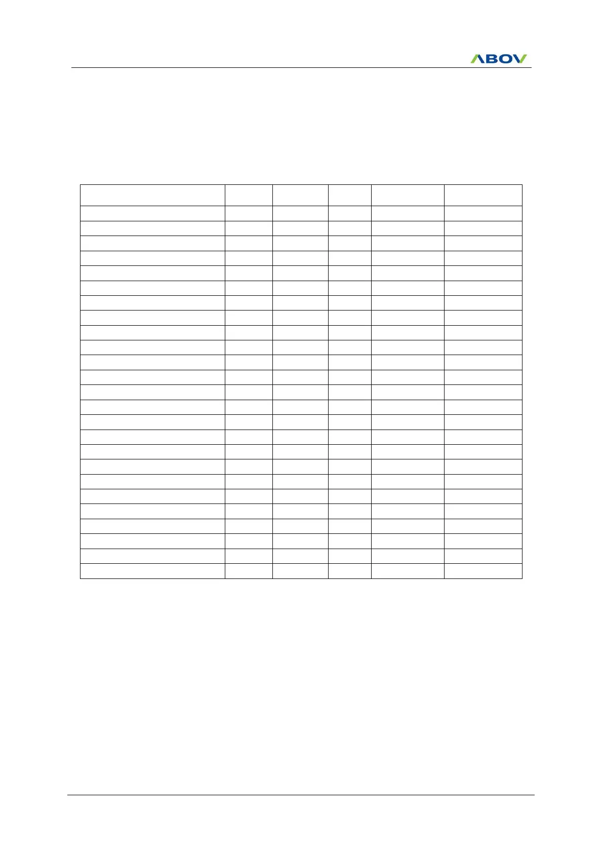
Table 10-2 Interrupt Vector Address Table
For maskable interrupt execution, EA bit must set ‘1’ and specific interrupt must be enabled by writing ‘1’ to
associated bit in the IEx. If an interrupt request is received, the specific interrupt request flag is set to ‘1’. And it
remains ‘1’ until CPU accepts interrupt. If the interrupt is served, the interrupt request flag will be cleared
automatically.
10.5 Interrupt Sequence
An interrupt request is held until the interrupt is accepted or the interrupt latch is cleared to ‘0’ by a reset or an
instruction. Interrupt acceptance always generates at last cycle of the instruction. So instead of fetching the
current instruction, CPU executes internally LCALL instruction and saves the PC at stack. For the interrupt
service routine, the interrupt controller gives the address of LJMP instruction to CPU. Since the end of the
execution of current instruction, it needs 3~9 machine cycles to go to the interrupt service routine. The interrupt
service task is terminated by the interrupt return instruction [RETI]. Once an interrupt request is generated, the
following process is performed.