MC96F6432
210 June 22, 2018 Ver. 2.9
11.12.14 USI0 I2C Mode
The USI0 can be set to operate in industrial standard serial communication protocols mode. The I2C mode uses
2 bus lines serial data line (SDA0) and serial clock line (SCL0) to exchange data. Because both SDA0 and SCL0
lines are open-drain output, each line needs pull-up resistor. The features are as shown below.
- Compatible with I2C bus standard
- Multi-master operation
- Up to 400kHz data transfer read speed
- 7 bit address
- Both master and slave operation
- Bus busy detection
11.12.15 USI0 I2C Bit Transfer
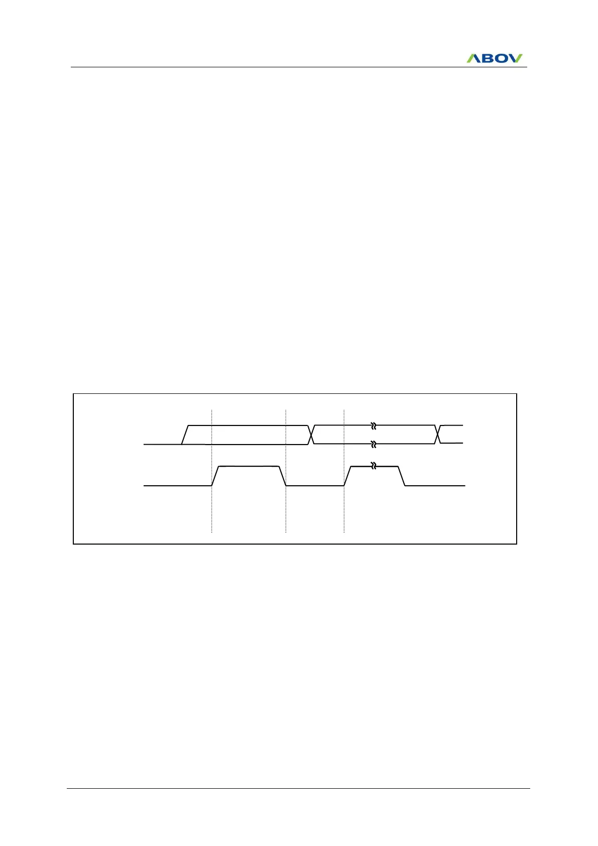
The data on the SDA0 line must be stable during HIGH period of the clock, SCL0. The HIGH or LOW state of
the data line can only change when the clock signal on the SCL0 line is LOW. The exceptions are START(S),
repeated START(Sr) and STOP(P) condition where data line changes when clock line is high.
Figure 11.67 Bit Transfer on the I2C-Bus (USI0)
Data line Stable:
Data valid
except S, Sr, P
 Loading...


