EasyManuals Logo

Abov MC96F6432Q User Manual

Default Icon
327 pages
To Next Page IconTo Next Page
To Previous Page IconTo Previous Page
Page #181 background imageLoading...
Page #181 background image
MC96F6432
June 22, 2018 Ver. 2.9 181
11.9 Buzzer Driver
11.9.1 Overview
The Buzzer consists of 8 bit counter, buzzer data register (BUZDR), and buzzer control register (BUZCR). The
Square Wave (61.035Hz~125.0 kHz @8MHz) is outputted through P13/SEG17/AN10/EC1/BUZO pin. The
buzzer data register (BUZDR) controls the buzzer frequency (look at the following expression). In buzzer control
register (BUZCR), BUCK[1:0] selects source clock divided by prescaler.
Table 11-15 Buzzer Frequency at 8 MHz
BUZDR[7:0]
Buzzer Frequency (kHz)
BUZCR[2:1]=00
BUZCR[2:1]=01
BUZCR[2:1]=10
BUZCR[2:1]=11
0000_0000
125kHz
62.5kHz
31.25kHz
15.625kHz
0000_0001
62.5kHz
31.25kHz
15.625kHz
7.812kHz
…
…
…
…
…
1111_1101
492.126Hz
246.063Hz
123.031Hz
61.515Hz
1111_1110
490.196Hz
245.098Hz
122.549Hz
61.274Hz
1111_1111
488.281Hz
244.141Hz
122.07Hz
61.035Hz
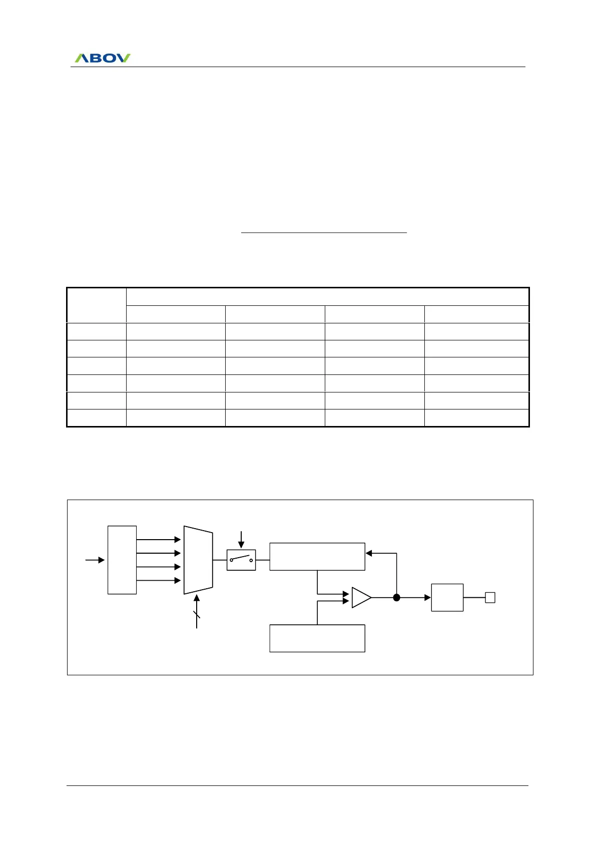
11.9.2 Block Diagram
Pre
scaler
fx
MUX
Counter
fx/32
fx/64
fx/128
fx/256
2
BUCK[1:0]
8-bit Up-Counter
BUZDR
Comparator
F/F
Clear
BUZO
BUZEN
Figure 11.48 Buzzer Driver Block Diagram
1)(BUZDRRatioPrescaler 2
Frequency Oscillator
(Hz)f
BUZ



Table of Contents

Questions and Answers:

Question and Answer IconNeed help?

Do you have a question about the Abov MC96F6432Q and is the answer not in the manual?

Abov MC96F6432Q Specifications

General IconGeneral
BrandAbov
ModelMC96F6432Q
CategoryMicrocontrollers
LanguageEnglish

Related product manuals