Machine Maintenance Procedures 3-31
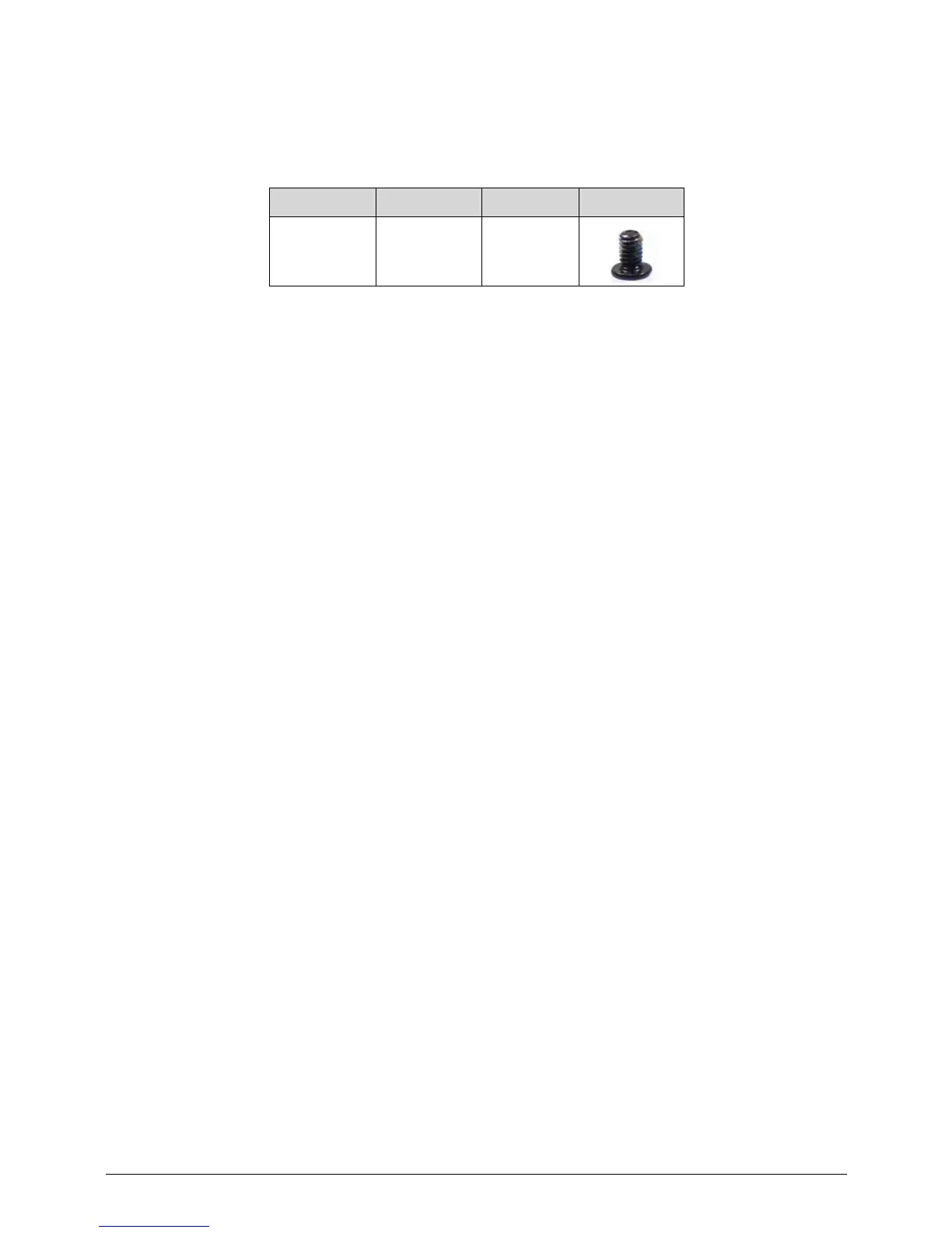
4. Install and secure screw (G) to bezel. (Figure 3-39)
5. Connect light sensor cable (E) to IO board connector (F).
6. Connect microphone cable (C) to IO board connector (D).
7. Connect 3G antenna cable (B) to IO board connector.
8. Install IO Board FPC.
ID Size Quantity Screw Type
G M2.0x3.0 1