This document describes the ACO Co.,Ltd. Vibration Level Meter, Type 3233 (Ver 1.3 remote), an instrument designed for measuring vibration levels.
Function Description
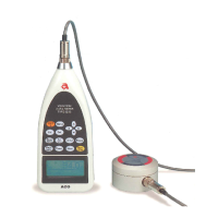
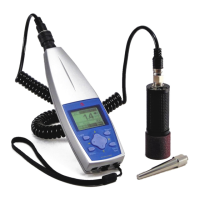
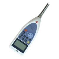
The Vibration Level Meter Type 3233 is a precision instrument used for measuring vibration levels. It can measure vibration level Lv, vibration acceleration level Lva, power average level Lveq, and hour rate vibration level Lx. The device is equipped with an RS-232C interface as standard, allowing connection to an external CPU for data transfer and control. Measurement results can be displayed as a bar graph and numerical values. The instrument is capable of storing up to 550 pieces of data in its memory.
Important Technical Specifications
Type Approval: No.TW162
Model: TYPE 3233
Product Name: Vibration Level Meter
Conforming Standard: Measurement Law JIS C 1510-1995
Measuring Range: 30 to 120dB
Measuring Frequency Range: 1Hz to 100Hz
Pick-up: 7833 (Vibration pick-up)
Level Range: 20 dB step 2-stage shifting, 30 to 90 dB, 50 to 110 dB
Linearity: 75 dB
Dynamic Characteristics: 0.63 s
Frequency Correcting Circuit: Vertical characteristics, Horizontal characteristics and flat characteristics
Measuring Items: Vibration level Lv, Vibration acceleration level Lva, Power average level Leq, Maximum value Lmax, Minimum value Lmin, Hour rate vibration level Lx(5 values)
Measuring Time: 1s, 3s, 5s, 10s, 1min, 5min, 10min, 15min, 30min, 1h, 8h, 24h, Manual (Maximum 199h59m59s)
Sampling Frequency: 256s(Leq), 64ms(Lmax, Lmin)
Lx Sampling Frequency: 64ms
Indicator: Liquid crystal (128 x 64 dot) with backlight
Digital Display: Numerical value displayed: 4 digits, Displaying frequency: 1s
Bar Display: Displaying frequency: 64 ms
Memory Function: Remaining capacity displayed in 4 stages, Computed values are stored in memory (Data of approx. 550 pieces)
Clock Function: Incorporated (Year/month/date; hour: minute: second) (Equivalent to +/- 1 minute monthly difference)
Temporary Stop Function: Ordinary temporary stop function
Calibration Signal: Electrical calibration by incorporated oscillator (31.5Hz sinusoidal wave)
AC Output: Output voltage: 316mVrms(F.S), Output resistance: 600Ω, Load resistance: 100kΩ or greater
DC Output: Output voltage: 2.5V (F.S), 0.25V/10dB, Output resistance: 50Ω, Load resistance: 100kΩ or greater
I/O Terminal: Interface: RS-232C (asymmetric), Data length: 8 bits, Stop bit: 1 bit, Parity: None, Transmission rate: 4800, 9600, 19200bps (for printer output and computer output)
Power Source: DC6V, 10%
Battery Life (continuous operation): Four 1.5V size-AA batteries or AC adaptor, Consumption current: Approx. 75mA (DC6V), When AC adaptor is used: Approx. 2VA, Alkaline battery: Approx. 20 hours, Manganese battery: Approx. 10 hours, Battery life is approx. 1/3 when backlight is lit
Operating Temperature and Humidity: -10 to +50°C, 30% to 90% (without condensation)
Dimensions: 85(W) x 220(H) x 46(D)
Weight: Approximately 380g (including batteries)
Usage Features
Safety Precautions:
- Always ensure the instrument is used in a safe manner to prevent injury to customers and others, and damage to property.
- Read the Operation Manual and attached documents before use.
- WARNING: Calls attention to procedures, practices, or conditions that could possibly cause death or bodily injury.
- CAUTION: Calls attention to procedures, practices, or conditions that could possibly cause bodily injury or damage to the instrument.
- Avoid using the instrument if it produces smoke, bad smell, or noise, as this can cause fire or shock hazard.
- Always turn off the POWER switch and unplug the AC adaptor (optional) from the outlet as soon as possible.
- To reduce risk of injury, take the instrument to a qualified serviceman when service or repair is required.
- Do not substitute parts or modify the instrument.
- Do not use the AC power adaptor except the optional AC-1026. Other types of adaptors may cause damage.
- Do not touch the plug of the AC adaptor (AC-1026) with wet hands to avoid shock hazard.
- Stop using the instrument if an object or liquid falls/spills into it, as this can cause fire or shock hazard.
- Keep the instrument away from children.
- Do not place it on an unstable place (shaky table or sloping place).
- Do not expose the instrument to moisture or dust.
- Do not put heavy objects on the instrument.
- Connect cables properly as instructed in the manual.
- Before moving the instrument, turn off the POWER switch and remove all wiring.
- For avoiding liquid spill, remove alkaline dry batteries when not in use for long periods.
Basic Operations:
- Display Modes: The device offers three display modes: normal screen, 3ch screen, and list screen, which can be switched using the screen switching key.
- Normal Screen Display: Shows the current vibration level (Lv) with a bar graph, range, and measurement time.
- 3ch Screen Display: Displays data for three channels simultaneously without a bar display. This is useful for viewing vibration level (acceleration level), power level, or hour rate vibration level.
- List Screen Display: Shows all data measured in one screen, including nine data points such as Vibration level (acceleration level), power level, and hour rate vibration level.
- Key Functions: The manual details the functions of each key: Light, Menu, Cal, Set, Meas. Time, Lv Lva, X,Y,Z, Range, Mode Leq·Lx, Pause, View, Start Stop.
- Backlight: The display (LCD) has a backlight that can be turned on by pressing the Light key. It automatically turns off after approximately 30 seconds to conserve battery life.
- Battery Installation: When the LCD displays "Low battery," new batteries should be installed. For long-term measurement, new batteries should be installed in advance. The device uses four AA batteries.
- AC Power Adaptor: The optional AC power adaptor (AC-1026) can be used. Power consumption is approximately 2VA.
- LCD Adjustment: LCD contrast can be adjusted via the Menu key.
- Calendar Adjustment: The date and time can be adjusted via the Menu key.
Measurement Operations:
- Vibration Level (Lv) Measurement: Switch the screen to the normal screen display using the View key. Select the channel (X, Y, Z) and range using the cursor and Range keys. The measurement display shows the digital value and a bar display.
- Vibration Acceleration Level (Lva) Measurement: Similar to Lv measurement, but the display changes from Lv to Lva when the Lv·Lva key is pressed.
- Power Average Level (Lveq) Measurement: Similar to Lv measurement. The display changes with the Mode Leq·Lx key. The Start·Stop key initiates and stops measurement, while the Pause key temporarily suspends and resumes it.
- Hour Rate Vibration Level (Lx) Measurement: Similar to Lv measurement. The display changes with the Mode Leq·Lx key. The Start·Stop key initiates and stops measurement, while the Pause key temporarily suspends and resumes it.
Menu Operations:
- The Menu key allows access to various settings, including Meas Mode, Interval, I/O, OUT Ch, LCD cont, date y/m/d, and time.
- Meas Mode: Can be set to Manual, Single, or Remote.
- Interval: Can be set to Off or Single.
- I/O: Can be set to Off, Print, or PC.
- OUT Ch: Can be set to X.
- LCD cont: Adjusts LCD contrast.
- Mode Set: Allows setting of DC Out, Meas time, View, baud rate, and Samp Time.
- Meas time: Options include 1s, 3s, 5s, 10s, 1m, 5m, 10m, 15m, 30m, 1h, 8h, 24h.
- View: Sets the display mode for hour rate vibration level (L05, L10, L50, L90, L95).
- Baud rate: Sets the transmission rate for printer and personal computer (4800, 9600, 19200).
- Samp Time: Sets the sampling time (Normal or 1s).
AC, DC Output:
- AC Output: Provides an alternate current signal of the frequency corrected output. Output voltage is 316mVrms (FS).
- DC Output: Provides a direct current (DC) signal of the effective value. Output voltage is 2.5V (FS), 0.25V/10dB.
- Tables are provided for full scale range (90dB and 110dB) with corresponding AC OUT (mVrms) and DC OUT (V) values.
Output to Personal Computer:
- The Vibration Level Meter can transfer measured data or data during measurement to a personal computer.
- Operating system support: Microsoft Windows 98SE/2000/XP/Vista/7. Windows 7 support 32bit, 64bit.
- Measured data can be collected after measurement or during measurement.
- Data is collected in a spreadsheet format.
- The collected data includes Date, Time, Direction/Range, Measurement, Lceq, Lmin, Lmax, L05, L10, L50, L90, L95.
Pin Connections and Extension Cable:
- The manual provides detailed instructions and diagrams for connecting the male connector of an extension cable to the device and attaching the pick-up to the female connector of the extension cable.
- It also describes how to detach the microphone from the body of the meter.
- Instructions are given for protecting the connector using self-fusing tape or plastic tape when the unit is exposed to water or rainwater.
Communication Command (RS-232C):
- Interface: RS-232C
- Transfer Speed: 4800, 9600, 19200bps
- Data Size: 8bit
- Stop Bit: 1bit
- Parity Check: None
- Format: CMD, DAT, CR, LF. Data is Variable size (ASCII), Command is 1Byte (ASCII).
- Command Table: Lists capital letters (PC command) and small letters (3233 command) for various functions like setting calendar, measurement condition, start/stop measurement, data acquisition, data request, calibration, backlight, independent range setting, filter setting, and Lp-value acquisition.
- Detail of Command: Provides outlines of functions for each command, including data formats (ASCII) and specific settings for transfer, configuration, measurement, data acquisition, data request, backlight, independent range setting, filter setting, and instantaneous value.
- Remote Mode: The device can be set to Remote mode manually via the Menu. In this mode, other key access is inhibited.
- Communication Timing: Diagrams illustrate the communication flow between the 3233 device and a PC for various commands like transfer configuration file, start/stop measurement, data acquisition, and Lp-value acquisition.
Maintenance Features
Calibration:
- The Vibration Level Meter can be periodically calibrated.
- Two types of calibration are available: internal oscillator and pick-up by an agitator.
- Calibration by Internal Oscillator: The oscillator (31.5Hz, sinusoidal wave) is incorporated in the Vibration Level Meter and allows for calibration.
- To calibrate, turn on the power switch, press the Cal key to switch into calibration status, press the Range key to select 110 dB with the cursor key, and then press the Range key to register.
- Turn the calibration volume on the side panel so that the level display indicates 110.0dB.
- Press the Cal key one more time to end the calibration.
- The relationship between display value and output voltage is provided in a table for AC OUT and DC OUT.
- Calibration with a vibration calibrator TYPE 2110 is used to set the vibration level meter to the vertical (Z) and vibration level (Lv) measurement states. Vertical (Z) vibration level (Lv) if the meter instruction value of the vibration level meter is 97.2 dB±1 dB (96.2 dB to 98.2 dB) is a pass.
Software Features (NA-0233-3 Vibration level meter / Data management software):
- This software collects data measured with an Aco Vibration level meter in a PC for processing.
- Operating Environment:
- Required CPU: MMX(R) Pentium(R) 120MHz or more
- Required OS: Windows(R)95/98/98SE/Me/2000/XP/Vista/7/8.1/10
- Memory: 32MB or more
- HDD free space available: 1MB or more
- Required interface: Serial port
- Software Features:
- Collected data is stored in a text format file for processing.
- If connected to a PC during measurements, data is transmitted to the PC.
- Necessary data, graphs, and reports can be created and used.
- Line Graph and Bar Graph: The software displays measurement data in line and bar graph formats.
- List Screen: Displays detailed measurement data in a tabular format.
- Installation: Copy the ACO Vibration level meter folder to the directory on the hard disk.
- Start up and Shut down: Double click the Type3233 icon in the folder, and the working screen appears.
- PC Operation: Move the cursor to an item on the screen for explanation. Data processing and PC operation are intuitive.
- Transmitting Data after Measurement:
- Settings for data measurements can be configured via the Menu key.
- Data can be transmitted to the PC after measurements.
- The software allows for setting communication speed (9600 BPS normal) and selecting between COM1 and COM8.
- Channel (X, Y, Z) can be selected, and Start Stop key transmits data.
- The screen below appears, and data transmission begins.
- Transmitting Data while Making Measurements:
- Data can be transmitted to the PC while measurements are being made.
- The Start/Stop key initiates data transmission for each measurement interval.
- The data is appended to data displayed on the PC screen.
- If the Start/Stop key is pressed during measurements, both measurements and transmission stop.
- Note: Transmitted data is not stored in the memory of the Vibration level meter. After transmission, data should be saved on the PC.
AUTO1 Measurement Guide (Appendix):
- Getting Started: Turn on the POWER switch, press the Menu key, and set the Meas Mode to Auto1.
- Measurement: Set the mode, and the unit can start measuring anytime.
- To start measurement, press the Start/Stop key. An arrow indicates the measurement screen upper left during a measurement stop. The measurement will automatically stop when memory is filled.
- Printing (Data Output):
- Turn on the POWER switch, press the Menu key to set I/O to Print, and press the Set key.
- Select Listing or Graphic Print.
- The software can print data in listing form or graphic form.
- The graphic printout displays Lv, Lva, Lveq, Lmin, Lmax, L05, L10, L50, L90, L95.
- Printing can be stopped by pressing the Stop key.
- The device calculates sampling data every 10 minutes, so six data per hour can be output. The graph is printed out from 24:00 to 0:00 in direction. If the data is of more than a day, it continues printing over the days.
- The listing printout displays VIBRATION Level, date, time, Lveq, Lmin, Lmax, and Lx values.
- Nine data points of every 10 minutes measurement are printed out in sequence.
- If measurement is stopped by pressing the Stop key, the data might be printed as "***(It shows shortage of data for calculating)."
How to Install the Vibration Pick-up:
- The manual provides guidance on how to install the vibration pick-up according to JIS standard 'Method of measuring the vibration level JIS Z 8735'.
- Installation Examples:
- Flat and Firm Ground: Please install the vibration pick-up on flat and firm ground (e.g., beaten ground, concrete, and asphalt).
- Hardened Ground: When the ground is hardened by beating in the block, install at a position higher than the surrounding ground to prevent soaking in water.
- Bad Examples: Avoid installing the pick-up in puddles or where there is a possibility of breakdown due to submersion.