WORKING WITH THE CONTROL UNIT 5-39
SB1391 Hardware and Setup Guide - Document revision no. 1.14
Action Effect of action
6. Set the Integrator Gain (D7) to
200.
7. Increase/decrease the Velocity
Gain (D8) until a good step
response profile is achieved.
A typical step profile for the velocity loop is shown
in FIGURE 5-38. (If the profile extends out of view,
click the Adjust vertical scale button in the
ACScope toolbar.)
Note
Avoid setting Vel (% of max) higher than 10%.
Action Effect of action
8. Click OK. The Velocity loop adjustment dialog box and the
ACScope window close.
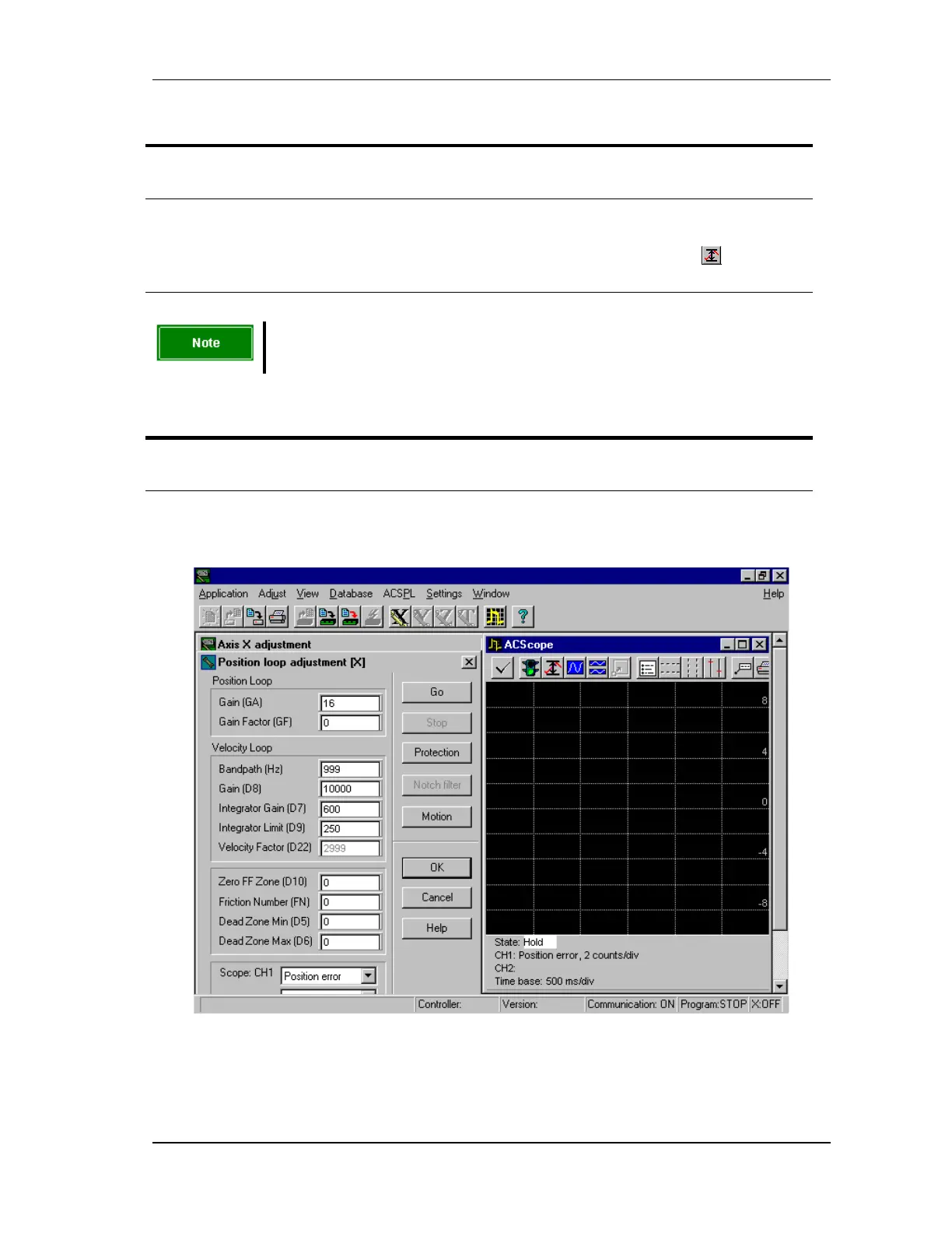
5.2.14. Step 8 - Position Loop
FIGURE 5-39 Position loop adjustment step