MOUNTING AND WIRING 4-29
SB1391 Hardware and Setup Guide - Document revision no. 1.14
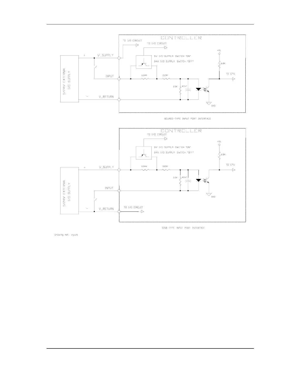
FIGURE 4-24 Input port interface
4.4.5.2. Digital Outputs
There are 8 non-dedicated, isolated outputs. An external supply must be connected between the
V_SUPPLY and V_RETURN pins.
External supply range: 5Vdc (±10%) or 24Vdc (±20%).
All the output circuits are protected by an internal automatic fuse. The V_OUT LED indicates that
the external supply is connected and the output circuits are working properly.
The maximum current for each output is 50mA (FIGURE 4-25). The maximum total current for
all eight outputs is 350 mA.
The digital outputs are protected against overloads (if one or several output currents
exceed more then 400mA) and against short circuits