4-30 MOUNTING AND WIRING
SB1391 Hardware and Setup Guide - Document revision no. 1.14
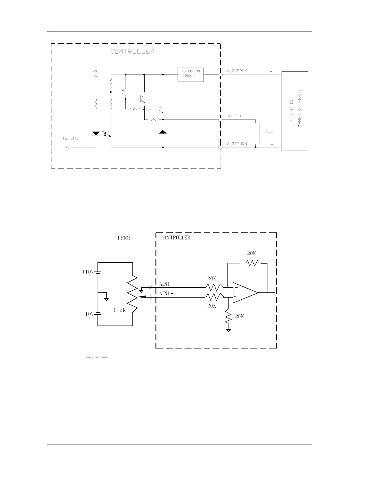
FIGURE 4-25 Output port interface
4.4.5.3. Analog Input
There is one differential analog input, which also acts as joystick input. The voltage range of the
analog input is ±10V. The potentiometer output must be connected to AIN1+. AIN1- must be
connected to the supply ground pin (FIGURE 4-26).
FIGURE 4-26 Joystick connection