WORKING WITH THE CONTROL UNIT 5-29
SB1391 Hardware and Setup Guide - Document revision no. 1.14
Action Effect of action
3. Click OK. The Protection parameters dialog box closes.
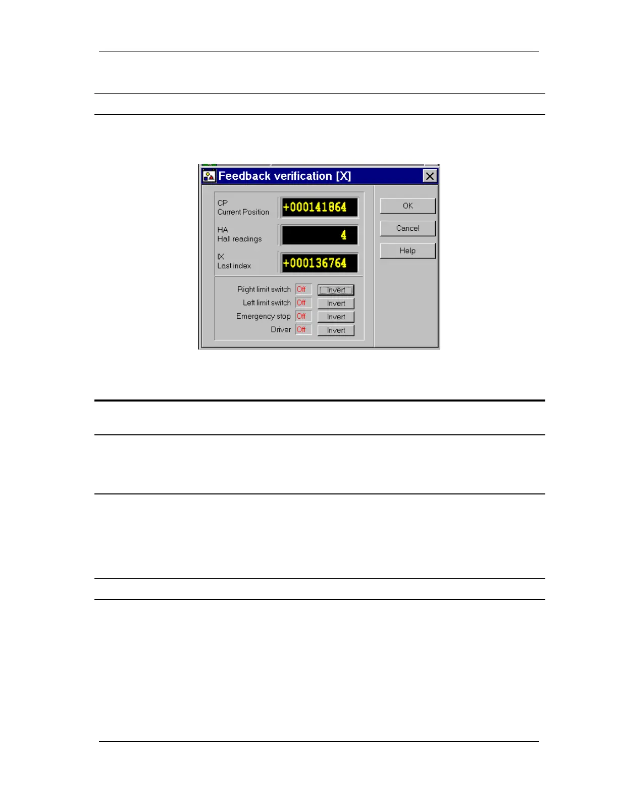
5.2.10. Step 4 - Feedback
FIGURE 5-27 Feedback verification step
Action Effect of action
1. Select 4. Feedback Verification and
click Step.
The Feedback Verification dialog box opens
(FIGURE 5-27).
2. Manually move or rotate the motor and
verify that the displayed feedback
values increase and decrease as
expected according to the needed.
When Current position (CP) counts up, the Hall
reading (HA) (if there are Hall sensors) should
display: 0, 1, 2, 3, 4, 5, 0, 1, 2, etc. If it doesn't, try
swapping two of the Hall wires.
3. Activate the safety switches: Right
limit switch, Left limit switch, and
Emergency stop.
Verify for each switch that the parameter value
changes to ON, when the switch is activated. If the
reverse is true (turning the switch on changes the
parameter value to OFF), click the appropriate
Inverse button to ensure that the parameter reflects
the actual state of the switch.
4. Click OK. The Feedback verification dialog box closes.
When the position feedback sensors are counting in opposite directions, an error message will
occur suggesting that you rotate the axis more slowly or check the wiring. The following is a list
of corrective measures:
• Slowly rotate the axis
• Make sure all cables are firmly secured
• Confirm connectivity and polarity (pin assignment)