5-30 WORKING WITH THE CONTROL UNIT
SB1391 Hardware and Setup Guide - Document revision no. 1.14
• Confirm that the proper feedback sensor type has been selected during the Motor Adjustment
step
• The following wire swaps may be necessary to match encoder and Hall direction:
• A+ and A-, or
• B+ and B-, or
• 2 pins on Hall
Note
If any safety devices are turned off during the adjustment session, they
should be turned back on upon session completion.
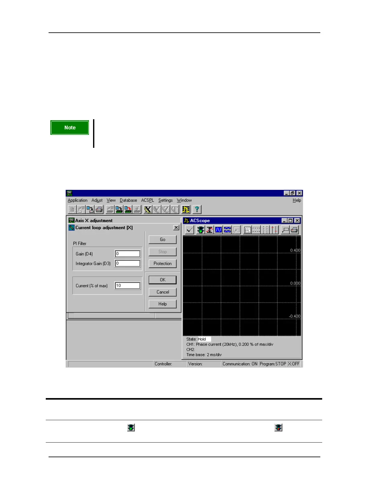
5.2.11. Step 5 - Current Loop
FIGURE 5-28 Current loop adjustment step
Action Effect of action
1. Select 5. Current loop adjustment
and click Step.
The Current loop adjustment dialog box and the
ACScope window open (FIGURE 5-28).
2.
Click the Start button (green
light) in the ACScope window.
The button function changes to Stop (red light).
The ACScope is now active.