INSTALLATION & MAINTENANCE MANUAL • X-MIND DC • (06) • 10/2018 • NXDCEN020F
Pag. 22 of 51
1. Take out from the packaging the wall plate and the drilling template 1.
2. Position the drilling template 1 on the radiographic system installation wall, at the required height (130cm from
the base in the suggested height).
3. Fix the template 1 with adhesive tape.
4. Check the holes for verticality and alignment with the floor, using a plumb line.
5. Mark the wall plate 8 fixing holes.
6. If required, mark the holes for the electric cables connecting the timer to the tubehead.
PLEASE NOTE
To prevent any flaking in the white coat and to control the centre distances between the holes, it is
advisable to start drilling with a tip Ø7, increasing this measure gradually.
7. Drill the fixing holes.
8. Remove the template 1 and insert the suitable anchor screws 2, according to the wall characteristics.
9. Unscrew the screw 3 and remove the plug 4 from the wall plate 8.
10. Withdraw the sliding cover 5.
11. Approach the wall plate 8 to the wall and insert the screws 7 with the relevant washers 6, then tighten
alternately.
12. Check that the wall plate 8 is steadily fixed to the wall.
PLEASE NOTE
If the wall is not perfectly levelled, put a suitable shim between the wall and the wall plate, so as to
prevent any possible deformations.
4.4. ASSEMBLING THE BRACKET
PLEASE NOTE
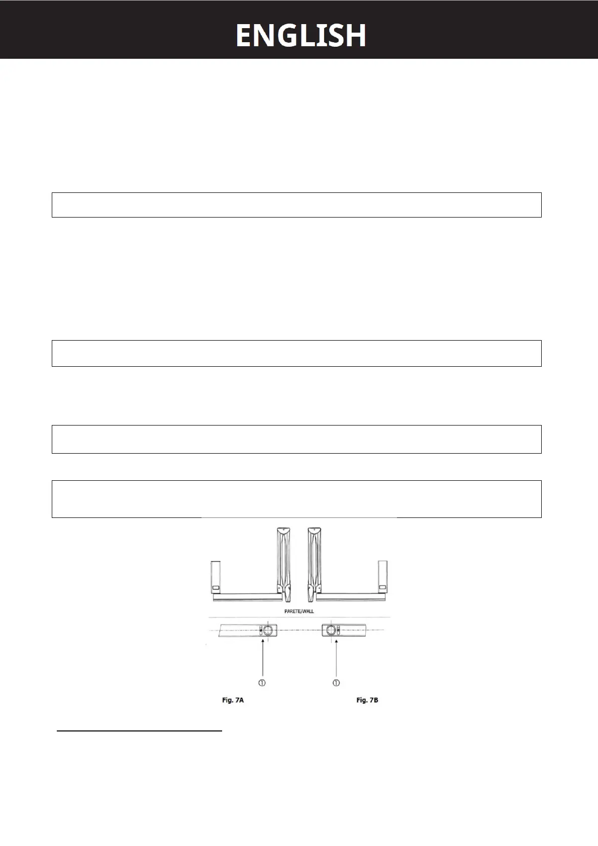
The 82,5cm and 110cm brackets are provided with a stop key 1 (Fig. 7A and 7B) to prevent the electric
cable from twisting.
PLEASE NOTE
Generally, the stop key is installed so that the equipment position at rest is on the right side of a
possible watcher standing in front of the wall plate (Fig. 7A). Should the position at rest be on the left
side, the stop key must be rotated by 180° (Fig. 7B).
ASSEMBLY INSTRUCTION (refer to Fig. 8)
1. Take out the bracket from the packaging.
2. Insert the bracket pin 3 into the wall plate 1 (upwards).
3. Insert the supporting rest 2.