INSTALLATION & MAINTENANCE MANUAL • X-MIND DC • (06) • 10/2018 • NXDCEN020F
Pag. 24 of 51
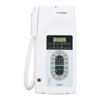
4.6. ASSEMBLING THE TIMER
CAUTION
Check that the cable runs are arranged in the timer installation wall; check the compliance of the power supply with
the installation specifications (refer to Chapter 3).
WARNING
Check that the rating data match the power supply voltage.
WARNING
When the timer is installed aside the wall plate, please consider what follows:
| the timer must be mounted on the left side of the wall plate;
the distance between timer and wall plate must be 2,5mm;
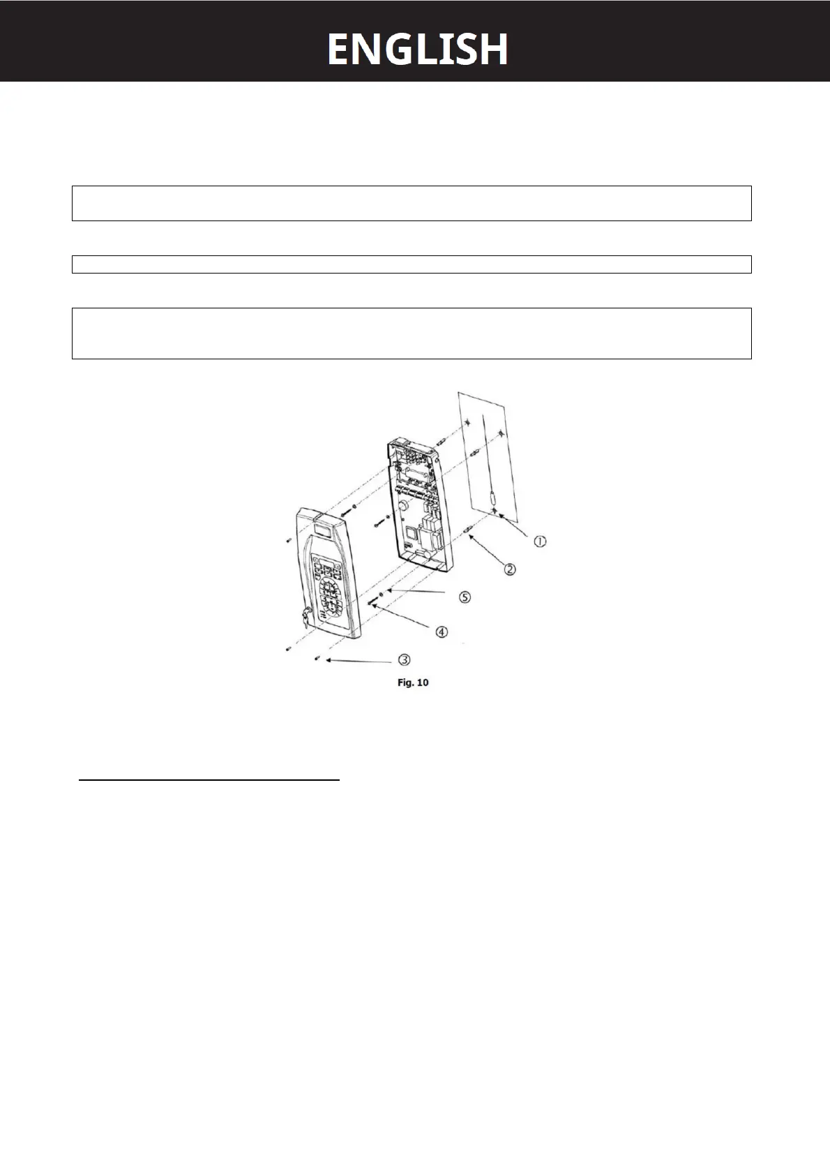
ASSEMBLY INSTRUCTION (refer to Fig. 10 - 11)
1. Take out the timer out of the packaging and take out the drilling template 1.
2. Position the drilling template 1 on the radiographic system installation wall, at the required height.
3. Fix the template 1 with adhesive tape.
4. Check the holes for uprightness and alignment with the floor, using a plumb line.
5. Mark the timer fixing holes on the wall using the drilling template.
6. If required, mark the holes for the electric cables connecting the timer to tubehead.
7. Drill using a Ø3 tip, then drill again with a Ø6 tip to prevent any flaking of the white coat.
8. Remove the template 1 and insert the suitable anchor screws provided 2.
9. Open the timer by unscrewing the three screws 8.
10. Withdraw the 26-pole connector from its seat to release both timer guards.
11. Approach the timer 8 to the wall and insert the electric feeding cables into the slot A or the slot B.
12. Insert the connection cables coming from the tubehead into the slot A or the slot B: when the timer is installed
aside the wall plate insert in between the rubber cover for the electrical cable.
13. Insert the cables of the X-ray signaling lamp for external use (OPTIONAL) and the cables of the remote-control
button (OPTIONAL) into the slot A or the slot B.
14. Approach the timer base 8 to the wall, matching the three anchor screws with the holes screw the screws with the
relevant washers.