INSTALLATION & MAINTENANCE MANUAL • X-MIND DC • (06) • 10/2018 • NXDCEN020F
Pag. 31 of 51
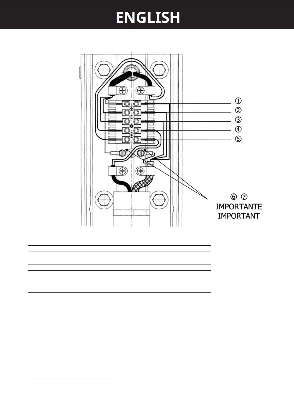
2. Proceed with the electric connection as shown below:
TERMINAL BOARD CONNECTION DIAGRAM
1 BROWN L = PHASE
2 YELLOW GREEN T = GROUND
3 BLUE N - NEUTRAL
4 BLACK COMMUNICATION
5 RED COMMUNICATION
6 YELLOW GREEN T = GROUND
7 YELLOW GREEN T = GROUND
THE COMMUNICATION CABLES ARE NOT POLARIZAED
3. Connect the pantograph cable shield to the grounding potential 6.
4. Connect the wall plate to the grounding potential 7.
5. Clamp the cables with the cable clamps provided.
6. Reassemble the terminal board cover.
CONNECTION INSTRUCTION TO THE TIMER
1. Connect the power supply cable to the terminal board α.